27
8009389/YN39/V3-0/2015-08| SICK OPERATING INSTRUCTIONS|GM35
Subject to change without notice
PROJECT PLANNING INFORMATION
3.3.2 Uncovering the duct
▸ If necessary, remove approx. 800 x 1500 mm (W x H) of the duct insulation to be able to
access the duct during subsequent work.
▸ Keep the insulation material removed for later refitting resp. provide new suitable
insulation material.
3.3.3 Installing the flange with tube
Notes on flange
installation
• Standard flanges and special versions
SICK delivers one flange with tube with 240 mm total length and 125 mm inner diameter
as standard. A version with 500 mm total length is available for installation locations with
thicker insulation or for stone stacks.
Special versions can be manufactured on request. Onsite flanges, including ANSI
flanges, can also be used.
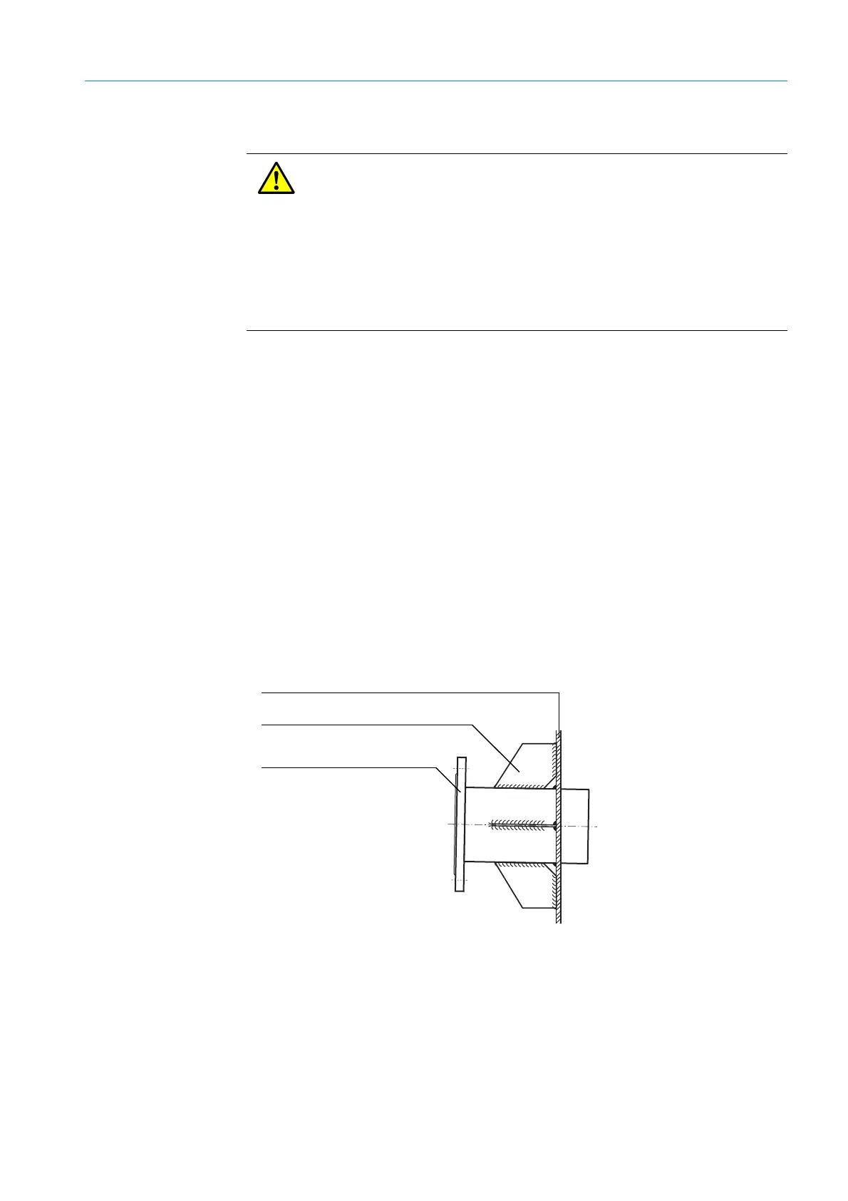
• Reinforcement with junction plates recommended
Due to the weight of the GM35 sender/receiver unit, it is recommended to reinforce the
flange tube onsite with junction plates.
Fig. 9: Reinforcing with junction plates
• Gas-carrying duct made of brick/concrete
An additional retaining plate with suitable opening should be manufactured for ducts not
made of steel and the flange with tube then welded into the opening.
CAUTION: Protective measures at the measuring point
▸ Always shut down the installation before any work on the duct!
▸ Secure parts to be separated with, for example, wire binding, to prevent
damage by falling objects.
▸ Take appropriate protective measures against hot, explosive gases or toxic
gases that could possibly escape from the duct.
▸ Always take all necessary safety precautions during welding work to prevent
explosions or fire in the duct atmosphere and on the duct insulation.
▸ If necessary, seal off the mounting flange with a cover securely until device
assembly (e.g. for overpressure in duct).
Duct wall (steel)
Reinforcing sheets (onsite)
Flange with tube