41
8009389/YN39/V3-0/2015-08| SICK OPERATING INSTRUCTIONS|GM35
Subject to change without notice
INSTALLATION
4.4 Electrical connection of system components
Onsite preparation for electrical installation has been described in “Preparations for electri-
cal installation”, page 30. The cables laid as described there are now connected to the sys-
tem components.
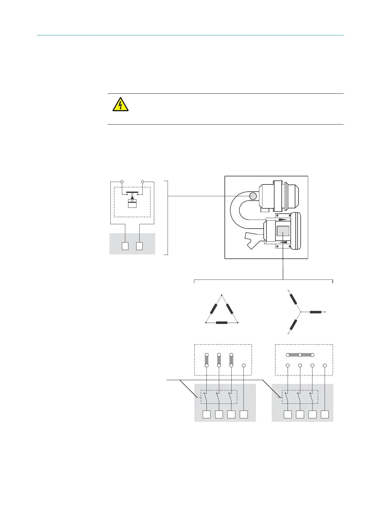
4.4.1 Electrical connection for the purge air unit
The technical data of the standard purge air unit are contained in
“Technical Data, Con-
sumables and Spare Parts”, page 128.
Fig. 17: Purge air unit: Electrical connections for blower motor and low-pressure monitor
WARNING: Observe safety information as well as relevant safety regulations!
During all work on electrical equipment, disconnect such equipment from the
mains, check that the equipment is potential free and make sure no third
person can switch the equipment back on again without authorization.
<
<
>>
=
=
<
<
=
=
>
>
7,333
<=>
=><7,
7,333
<=>
=><7,
Low-pressure monitor
connection
SLV
UW
Terminal box
blower motor
Delta connection
Star connection
Motor circuit
breaker
NO contact, switches at
approx. 35 hPa
underpressure