76
8009389/YN39/V3-0/2015-08| SICKOPERATING INSTRUCTIONS|GM35
Subject to change without notice
START-UP
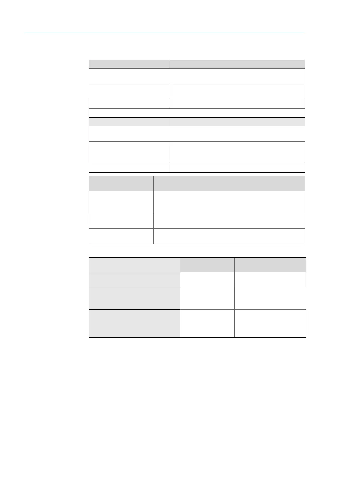
7.2.1 Required tools and materials for the installation
For adjustment:
Tools Required for
2 x 24 mm open-ended
spanners or ring spanners
Installing the measuring probe on the duct
1 x 19 mm open-ended spanner
or ring spanner
Installing the measuring probe on the SR-unit and
optical adjustment
Allen key set
Insulated screwdriver set Electrical connection work
Materials
Optical cleaning cloths without
detergents
SICK Part No. 4003353
Adhesive, recommendation:
quick-drying epoxy resin
adhesive
Attaching the fixing bolts on the SR-unit.
Personal protective equipment Work on gas ducts with hot or aggressive sample gases.
Fixing parts (included in
scope of delivery)
Required for
4 x M16 x 60 screws with
washers and self-locking
nuts
Fixing the probe on the duct-side flange.
3 x nuts with washers
and 10 cup springs each
Fixing the probe on the SR-unit (compare
page 80).
Sealing ring
Sealing the connection between measuring probe and
SR-unit.
Required material
Adjustment at the
measuring point
Adjustment at a different
location
Angle flange
(Part No.: 2017833)
x
Test bracket provided by the
customer (replacement for angle
flange)
x
x
Power supply cable with suitable
device connector, 1 x for SR-unit, 1 x
for GPP measuring probe, Part No.
2017519
x