139
8009389/YN39/V3-0/2015-08| SICK OPERATING INSTRUCTIONS|GM35
Subject to change without notice
TECHNICAL DATA, CONSUMABLES AND SPARE PARTS
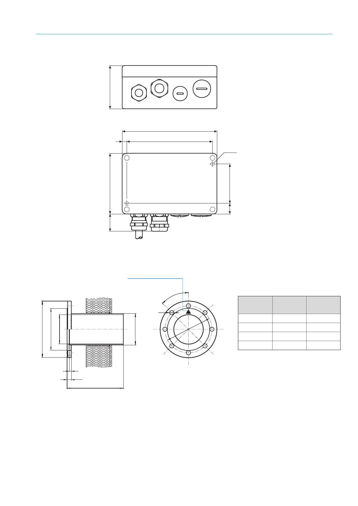
11.2.8 Terminal box for CAN bus connection, dimension drawing
Fig. 78: Terminal box dimensions for CAN bus (option); Part No. 2 031 677
11.2.9 Flange with tube, dimension drawing and Version Table
Fig. 80: Flange with tube for installing the GM35 SR-unit on the duct
PG11
PG13.5
52
1136
125
14
8023 57
∅ 5
ø 240
ø 178
ø 125
ø 133
14
240/500
8
18
4
5
°
200
Marking
points upwards
Versions deliverable from stock
Alternatively, an ANSI flange provided by the
customer can be used.
Part No. Material Length
[mm]
2016807 ST37 240
2016808 1.4571 240
2017785 ST37 500
2017786 1.4571 500
Fig. 79: Flanges with tube for the GM35
available from stock