44
8009389/YN39/V3-0/2015-08| SICKOPERATING INSTRUCTIONS|GM35
Subject to change without notice
INSTALLATION
4.4.3 Electrical connection of the evaluation unit
Laying cables to the evaluation unit and the cable specifications have already been
described in
“Preparations for electrical installation”, page 30, in particular in “Cable rout-
ing diagram”, page 33.
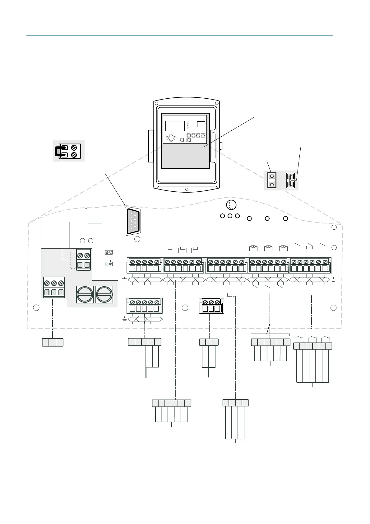
Fig. 19: Connections on the evaluation unit (cabling provided by the customer)
+ – + – + –
+ – + – + –
+ –
+ – + –
PE
N
L1
PE N L1
V 42+
H NAC
L NAC
V 42+
H NAC
L NAC
CAN GND
CAN H
CAN L
CAN GND
+– +–+–
115/230 V AC;
50/60 Hz
(3 x 1.5
2
)
+– +–+–
12
12 3
Power
+5V +24V
Power CAN
+24V
+ – H L GND
Digital in
CAN2
Terminator
Analog in
0.. 20mA
100 100 100
40..60Hz
230V
or
115V
AO1 AO2 AO3DI1 DI2 DI3 AI1 AI2 AI3
Sensor
DO1 DO2 DO3
Digital out
AC/DC 48V 30VA 1A
Analog out
0.. 20mA
Sensor
CAN2
Fuse 2.5 AT 250V
PE N L1
Tp
Enter meas
diag par cal maint
Operation
Service
Warning
Malfunction
GM 35
Evaluation Unit
RS 232
Plug this bridge for 115 V or 120 V voltage supply.
48 V AC/DC; 60 VA,
1 A (6 x 0.75
2
)
Relay outputs
0...20 mA (6 x 0.75
2
)
Analog outputs
0...20 mA (6 x 0.5
2
)
Analog inputs
Failure
1)
Maintenance request
2)
Function control
2)
Check cycle
Free assignment
Jumper not connected
(not activated)
Connections circuit board
Cast-metal enclosure shown
1)
NC contact
2)
NO contact
Cable (twisted, shielded) to
SR-unit or terminal box
Cable (twisted, shielded)
to SCU
RS232 connection
CAN2
terminator
Jumper connected
(activated)