12
8009389/YN39/V3-0/2015-08| SICKOPERATING INSTRUCTIONS|GM35
Subject to change without notice
PRODUCT OVERVIEW
2.1.2 Overview of standard components
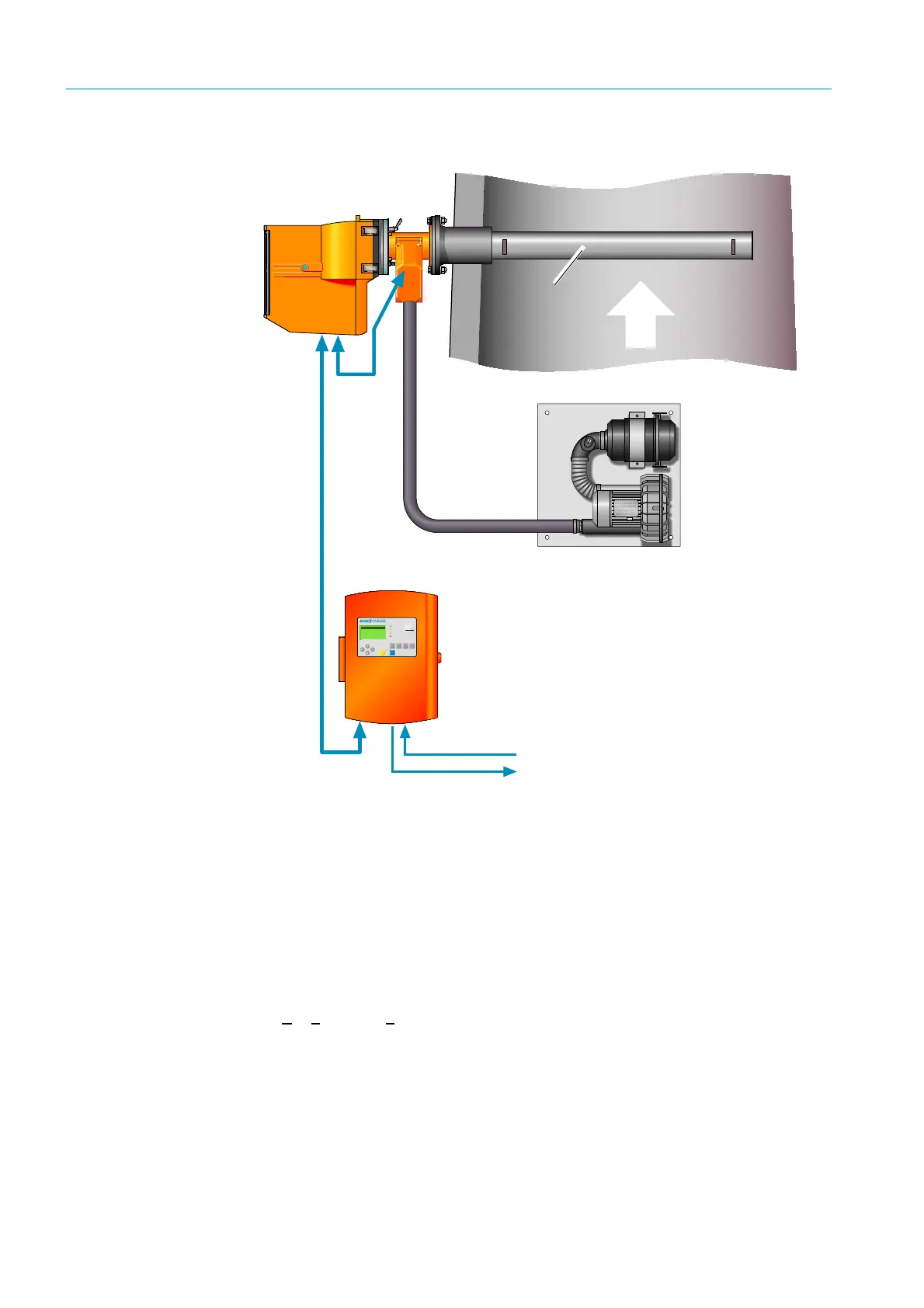
Fig. 1: GM35 system overview
• Sender/receiver unit (SR-unit)
Contains the main optical and electronic subassemblies of the measuring system. Records
gas concentrations, calculates measured values, measures components CO or N
2
O, CO
2
and H
2
O; both singly and simultaneously in combinations.
• Measuring probe
Measuring probes are available in open design versions with integrated purge air guidance
system (GMP) as well as versions with a gas-permeable diaphragm not requiring purge air
(GPP: G
as Permeable Probe). Both versions are described from page 14 onwards.
• Purge air unit
Provides purge air supply for the SR-unit with a GMP measuring probe (open design) and
protects against contamination and high gas temperatures. The blower types for the
SR-unit resp. reflector are designed differently depending on the application.
maintcalpardiag
GM 35
Evaluation Unit
CO
CO
2
H
2
O
mg/
m
3
236
Ref. conditions
Hum: wet
Measuring
Operation
Service
Warnin
Malfunction
Purge air unit SLV4
(not required when
using GPP measuring
probes)
GM35 sender/receiver unit
with GMP measuring probe
Temperature
sensor
Evaluation unit
EvU
CAN bus
CAN
Inputs/outputs
analog, binary
Interfaces to plant
peripherals:
•Host computer
•Sensors
• Measured data
processing
• Status signals