90
8009389/YN39/V3-0/2015-08| SICKOPERATING INSTRUCTIONS|GM35
Subject to change without notice
START-UP
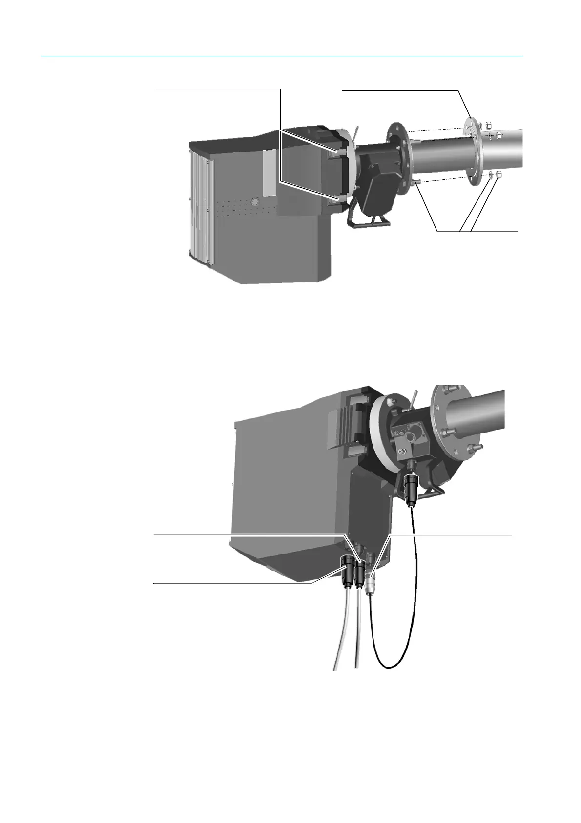
Fig. 55: Installing the SR-unit with measuring probe on the duct-side flange
7.6.4 Electrical connections and checking the optical alignment
The cables laid previously and the cables connected in the connection unit (
see “Cable
routing diagram”, page 33) as well as the CAN bus cable for the measuring probe are now
connected to the SR-unit.
Fig. 56: Cable connections on the underside of the SR-unit
Flange with tube (duct-side)
M16x60 screws with
nuts and each with
one washer and snap
ring
Quick-release fasteners
Power supply cable
for SR-unit
CAN bus cable to
evaluation unit
(possibly via
terminal box)
CAN bus cable to
measuring probe