26
8009389/YN39/V3-0/2015-08| SICKOPERATING INSTRUCTIONS|GM35
Subject to change without notice
PROJECT PLANNING INFORMATION
3.3 Initial onsite installation
The following work can be carried out by the customer's technicians. Requirement: The
project planning checklist has been processed beforehand.
3.3.1 Assembly preparation at the measuring point
This Section describes the welding work on the duct including making fixing elements
onsite.
Already completed? If you have already used the separate document “Product Information and Planning Guide”
to complete the work described here prior to delivery of the device, please check that the
work done corresponds to the following instructions.
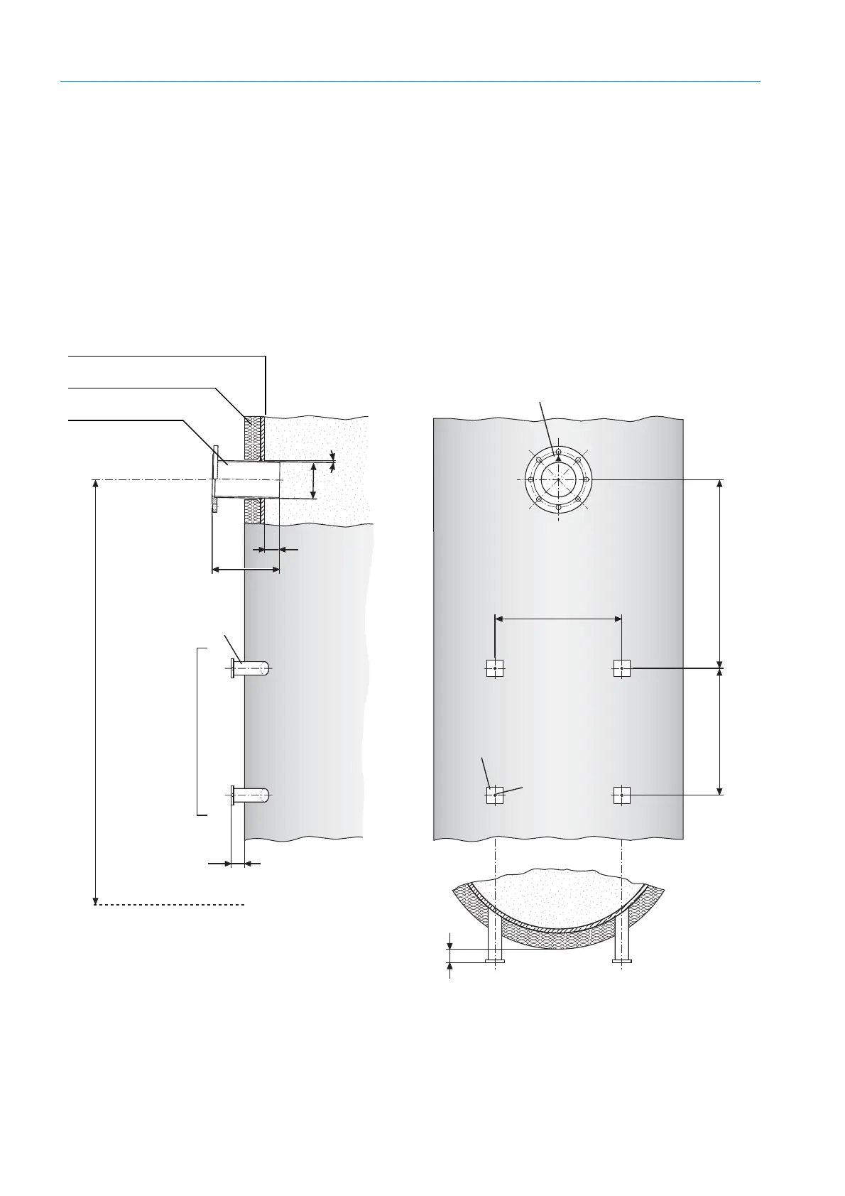
Fig. 8: Installation recommendation: Mounting flange and purge air unit (duct diameter not
representative)
30
L
50
470
M10
Ø133
1
°
FL. 60x8x60
DIN 174
min. 700
Stahlrohr
50 x 5
DIN 2391
▴
: Markierung für Einbaulage
in Strömungsrichtung zeigend
Befestigung der Spüllufteinheit
1,3 – 1,5 m
50 mm Überstand bei kreisförmigem Kanalquerschnitt
Arbeitsbühne/Plattform
470
Duct wall (steel)
Duct insulation
Flange with tube,
standard: L = 240 mm
▴ : Marking for fitting position,
pointing in flow direction
50 mm protrusion for circular duct cross-section