77
8009389/YN39/V3-0/2015-08| SICK OPERATING INSTRUCTIONS|GM35
Subject to change without notice
START-UP
7.3 Mechanical preparations for the SR-unit and reflector
7.3.1 Checking the scope of delivery
▸ Check the exterior of the SR-unit and measuring probe to ensure they are not damaged.
▸ Make sure the supply voltage on the type plate of the SR-unit complies with the plant
conditions.
▸ If a GPP measuring probe is to be used, also check the supply voltage specified on the
type plate of the measuring probe.
The supply voltage of the GM35 SR-unit and measuring probe can be changed between
115 V and 230 V on site by the SICK Service when necessary.
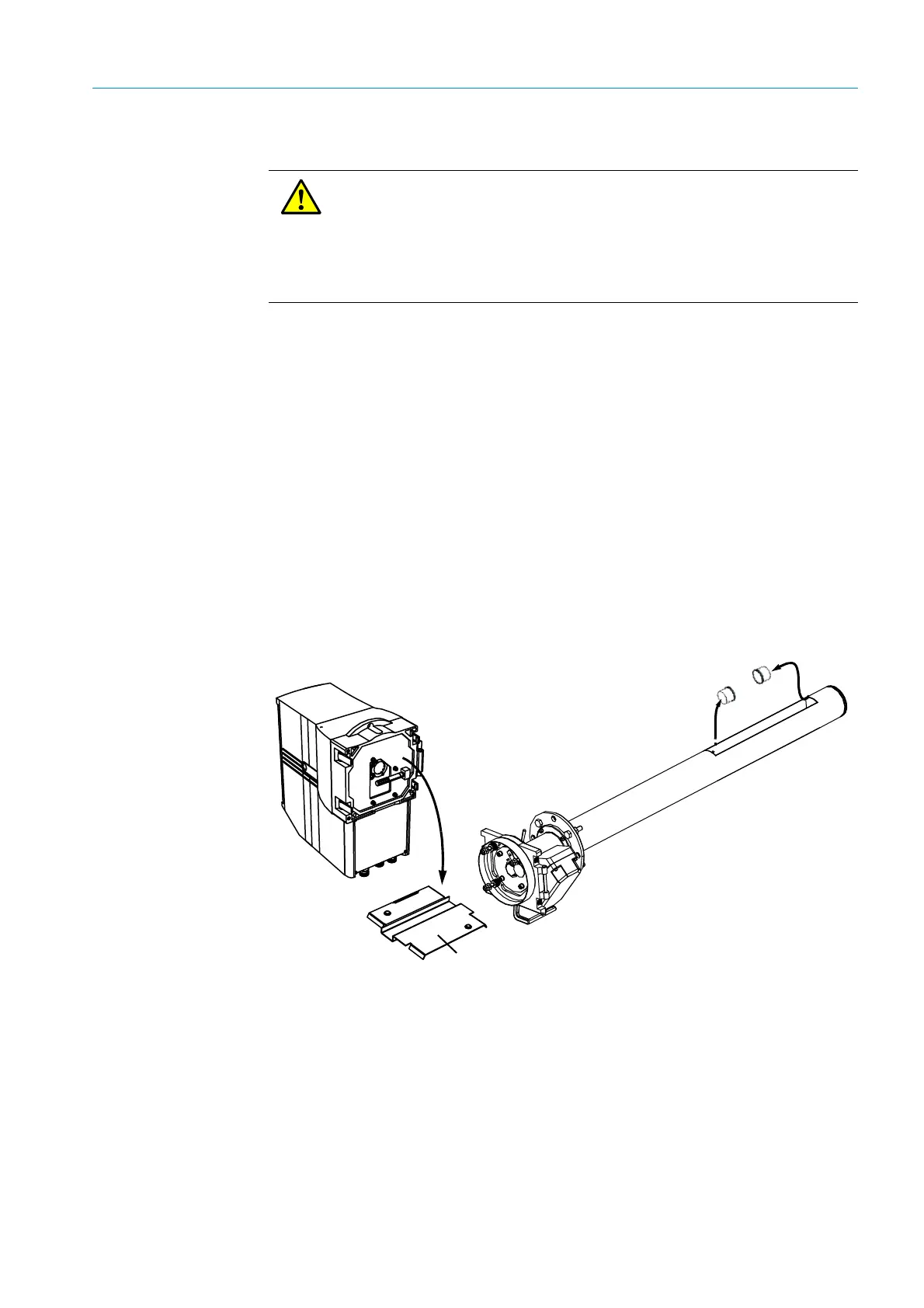
7.3.2 Transport safety devices
▸ Remove the transport safety devices shown below as well as any protective stickers,
marked as such, depending on the device version.
▸ The front cover of the SR-unit is clamped between the flange fixture and enclosure. To
remove it, open the four quick-release fasteners and swivel the flange fixture up (see
Fig.). Keep the transport safety devices as required.
Fig. 48: Transport safety devices to be removed from the SR-unit and measuring probe
WARNING: Avoid hazards through sample gases!
To avoid health hazards, the following work step may not be carried out during
the preparation described in this Section but first within the scope of the
respective descriptions in the following Sections.
– Connecting the power supply to the SR-unit
– Fitting an angle flange or the measuring probe on the sample gas duct
Plastic protective caps on the
openings in the measuring gap on
GMP measuring probes
SR-unit front cover