79
8009389/YN39/V3-0/2015-08| SICK OPERATING INSTRUCTIONS|GM35
Subject to change without notice
START-UP
7.4 Aligning the measuring probe in flow direction
The measuring gap must be aligned in gas flow direction so that the gas can flow through
unhindered. The SR-unit should normally be operated in a vertical position and, because
the alignment of the device flange to the SR-unit is fixed, the measuring probe must then
be aligned by rotating the device flange.
If the flow angle for the measuring system is already known at the factory on the basis of
the project planning data, the probe is usually aligned on delivery. However, alignment can
also be carried out onsite as described in the following.
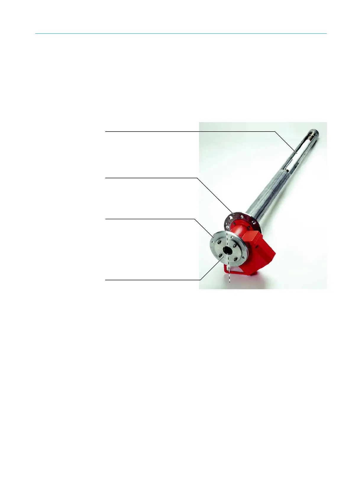
Fig. 49: Measuring probe (e.g. GPP): Flange and angular alignment of the measuring gap
The SR-unit should be mounted vertically and therefore the alignment of the device flange
serves as reference for the vertical axis shown by the “top” and “bottom” points on
page 79. The angle of rotation of the probe against the vertical axis of the device flange is
equal to the angle of the gas flow direction against the vertical axis and, therefore, to the
alignment of the flange with tube on the duct side.
Changing the alignment of the measuring probe:
1 Using an Allen key, loosen the screws on the fixing ring that secures the device flange to
the measuring probe.
2 Turn the device flange so that the measuring gap is aligned against the vertical axis of
the SR-unit (
see page 79) in the flow direction of the sample gas duct.
3 Fix the device flange in this position by tightening the screws on the fixing ring again.
Measuring gap
The measuring gap is aligned in
sample gas flow direction.
Mounting flange
For mounting on the duct-side flange
with tube already mounted in sample gas
flow direction during onsite preparations,
see page 36.
Device flange
The alignment of the device flange on
the SR-unit is determined by the three
holes and spacer bolts of the SR-unit.
The vertical axis of the SR-unit to the
device flange is shown by the broken
line in the Figure.
Fixing the device flange
The device flange can be rotated
steplessly against the measuring probe
by loosening the fixing screws.
Top
Bottom