91
8009389/YN39/V3-0/2015-08| SICK OPERATING INSTRUCTIONS|GM35
Subject to change without notice
START-UP
1 Connect the CAN bus cable between SR-unit and measuring probe to the socket
provided on the measuring probe.
2 Connect the prefabricated or preinstalled cables to the underside of the SR-unit as
shown on
page 90.
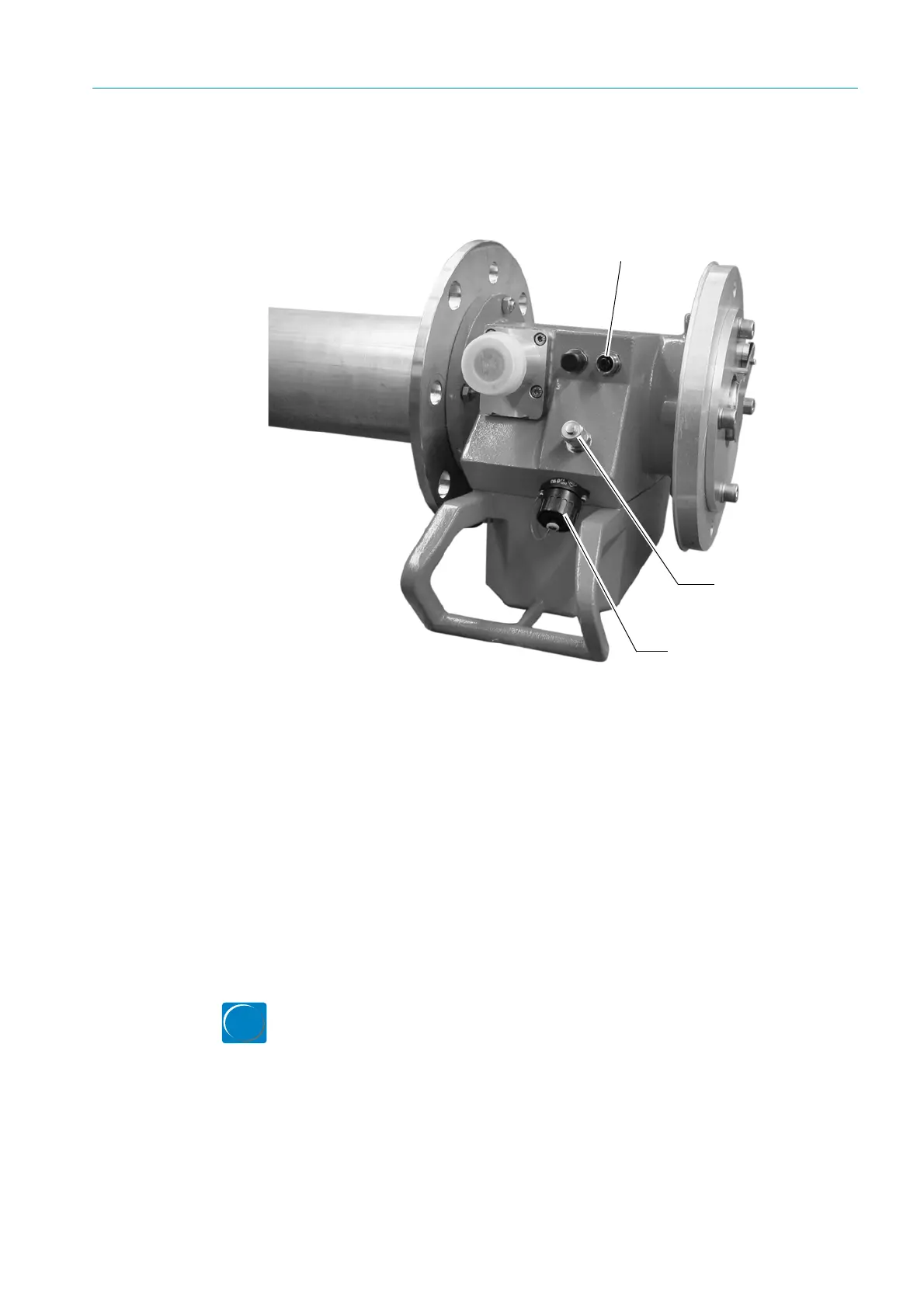
Fig. 57: Connections on the GMP probe
3 Make sure all screwed connections on both the SR-unit and measuring probe are tight
so that the plug-in connectors sit securely.
4 Connect the functional earth cable to the screw-type terminal provided.
5 Switch the power supply on.
6 When using a GPP measuring probe that was supplied with power via a temporary cable
during installation, connect the second prefabricated power supply cable with 4-pole
round plug-in connector to the measuring probe instead of the temporary cable; see
wiring diagram on
page 33. Make sure that the power supply of the GPP measuring
probe is not interrupted too long.
7 With the measuring system installed, and after a sufficient wait time of approx.
30 minutes to ensure that the operating temperature has been reached, check the
optical alignment again.
8 To do this, call up menu Adjust Probe again on the EvU and check the displayed values,
see page 86.
9 Reactivate Measuring mode:
– Quit the Diag menu with <-- back or
–Press meas
Regular measuring operation now starts.
Filter monitor connection (SLV 4)
CAN connection to SR-unit
Pressure sensor
connection