43
8009389/YN39/V3-0/2015-08| SICK OPERATING INSTRUCTIONS|GM35
Subject to change without notice
INSTALLATION
Wiring in terminal box
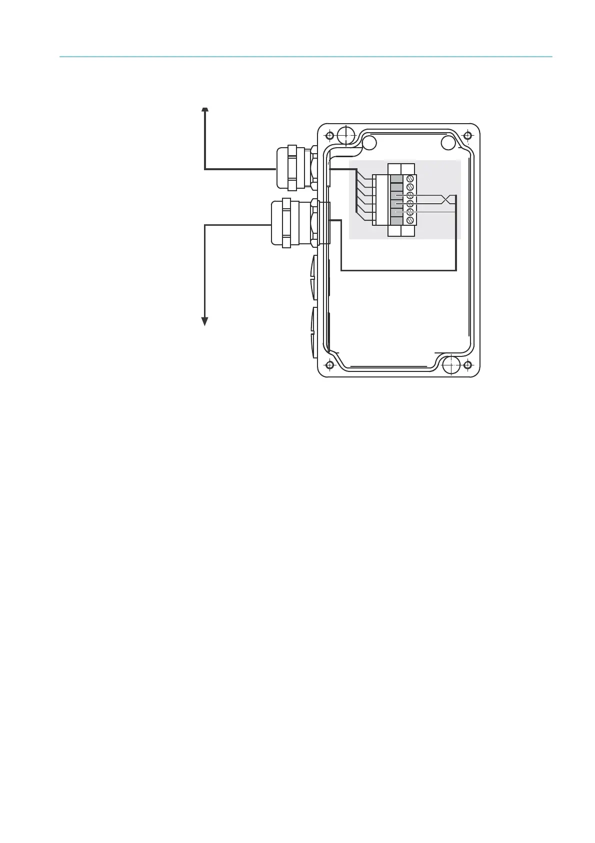
Fig. 18: Terminal box for CAN bus connection with a cable length between SR-unit and evaluation
unit longer than 19 m
Wiring the connections in the terminal box
1 Lead the CAN bus cable provided by the customer through the free screw fitting of the
terminal box.
2 Connect the shield on the screw fitting to the enclosure of the terminal box.
3 Connect the wires to the terminal strip as shown on
page 43; make sure a twisted wire
pair is used for CAN-H and CAN-L.
WR
NY
`L
NU
IU
^O
*(5/
*(53
*(5.5+
Prefabricated cable
with plug, 4 m long,
to SR-unit
Cable provided by the
customer for the
evaluation unit