45
8009389/YN39/V3-0/2015-08| SICK OPERATING INSTRUCTIONS|GM35
Subject to change without notice
INSTALLATION
Make connections
1 Open enclosure door of evaluation unit.
▸ Lead the signal cable for inputs and outputs through the PG screw fittings on the EvU
enclosure floor and wire according to
“Connections on the evaluation unit (cabling pro-
vided by the customer)”, page 44.
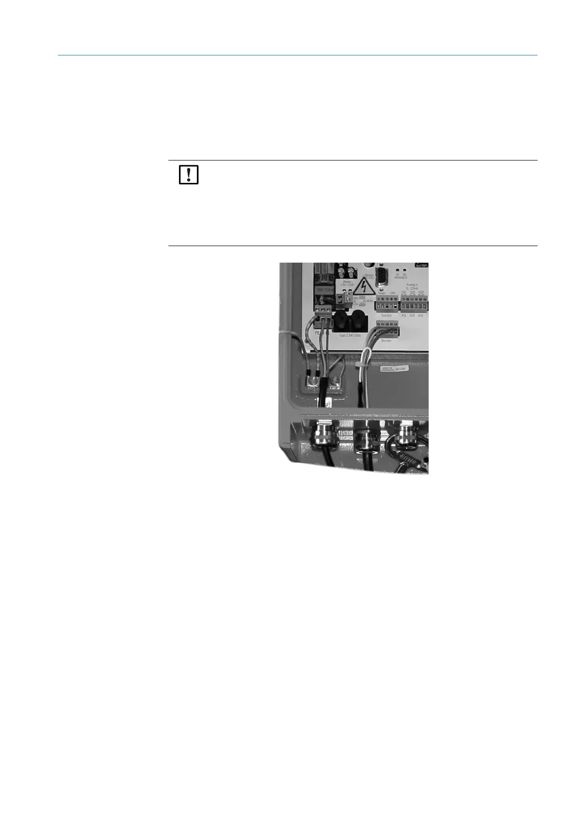
Fig. 20: EvU power connection
GM35 SR-unit or terminal box connection:
▸ If the customer supplied CAN cable is used, connect the wires to terminal strip “Sensor”,
see page 44. Do not connect +24 V and GND (earth).
Connection to the SCU (System Control Unit):
▸ If the customer supplied CAN cable is used, connect the wires to terminal strip “CAN2”,
see page 44.
▸ Activate the terminating resistor of the CAN bus when the EvU is connected to the start
or end of the CAN bus, see page 44:
▸ Connect the jumper for the CAN2 terminator.
▸ Deactivate the terminating resistor for the CAN bus when the EvU is not connected to
the start or the end of the CAN bus, see page 44:
>>>
No jumper may be connected to the CAN2 terminator.
Observe connection values for power supply!
The evaluation unit is configured to 230 V AC on delivery.
▸ Plug the respective bridges for 115 resp. 120 V AC as shown on the
connection plate of the evaluation unit.
▸ Make sure the power supply has been installed (
“Electrical connection of
the evaluation unit”
) in accordance with the specifications (observe
national specifications) and that the power is switched off.