131
8009389/YN39/V3-0/2015-08| SICK OPERATING INSTRUCTIONS|GM35
Subject to change without notice
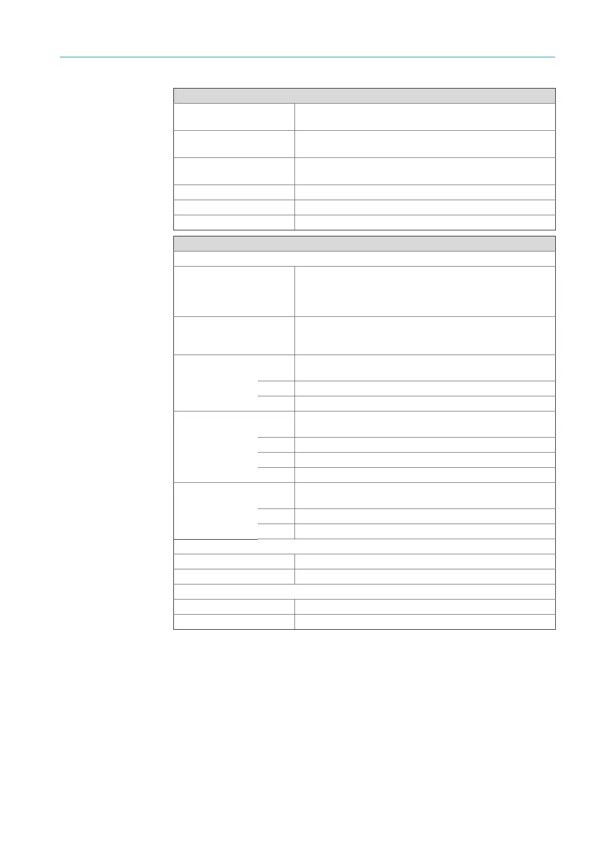
TECHNICAL DATA, CONSUMABLES AND SPARE PARTS
Purge air unit
Power supply (three-phase)
● Δ 200–240 V, Y 345–415 V at 50 Hz
● Δ 220–275 V, Y 380–480 V at 60 Hz
Rated current
● Δ 2.6 A / Y 1.5 A at 50 Hz
● Δ 2.3 A / Y 1.3 A at 60 Hz
Motor rating
● 0.35 kW at 50 Hz
● 0.45 kW at 60 Hz
Flow rate Min. 40 m
3
/h
Dimensions (W x H x D) 550 x 550 x 270 mm
Weight 14 kg
GM35 Evaluation unit (EvU)
Connections/interfaces
Data transmission within the
GM35 measuring system
CAN bus
• Max. line length 1000 m
• Electrically isolated
• Connects EvU, SR-unit, measuring probe
Service interface for PC RS 232
• Connection via 9-pole Sub-D socket
• Modem capability
Analog outputs 3 pcs Output range: 0–20 mA, max. 500 Ω, electrically isolated, live zero
adjustable to 4 mA
A1–A3 Measured values; assignment can be set individually
Analog input 0 ... 20 mA, 100 Ω
Status outputs 3 pcs Relay, NO contacts
DC max. 30 W, 48 V, 1 A; AC max. 60 VA, 48 V, 1 A
R1 Failure
R2 Maintenance request
R3 Function control
Status inputs 3 pcs Inputs for connecting potential-free contacts (loadable with 24 V;
supplied by GM35 evaluation unit)
E1 Check cycle
E2 Autocal GM35 in preparation
Power supply
Voltage/frequency 115/230 V AC ±10%; 50/60 Hz
Power input 50 VA max.
Dimensions, weight, protection class
Protection class IP 65 / NEMA 4x
Dimensions Dimension drawing,
see page 135