85
8009389/YN39/V3-0/2015-08| SICK OPERATING INSTRUCTIONS|GM35
Subject to change without notice
START-UP
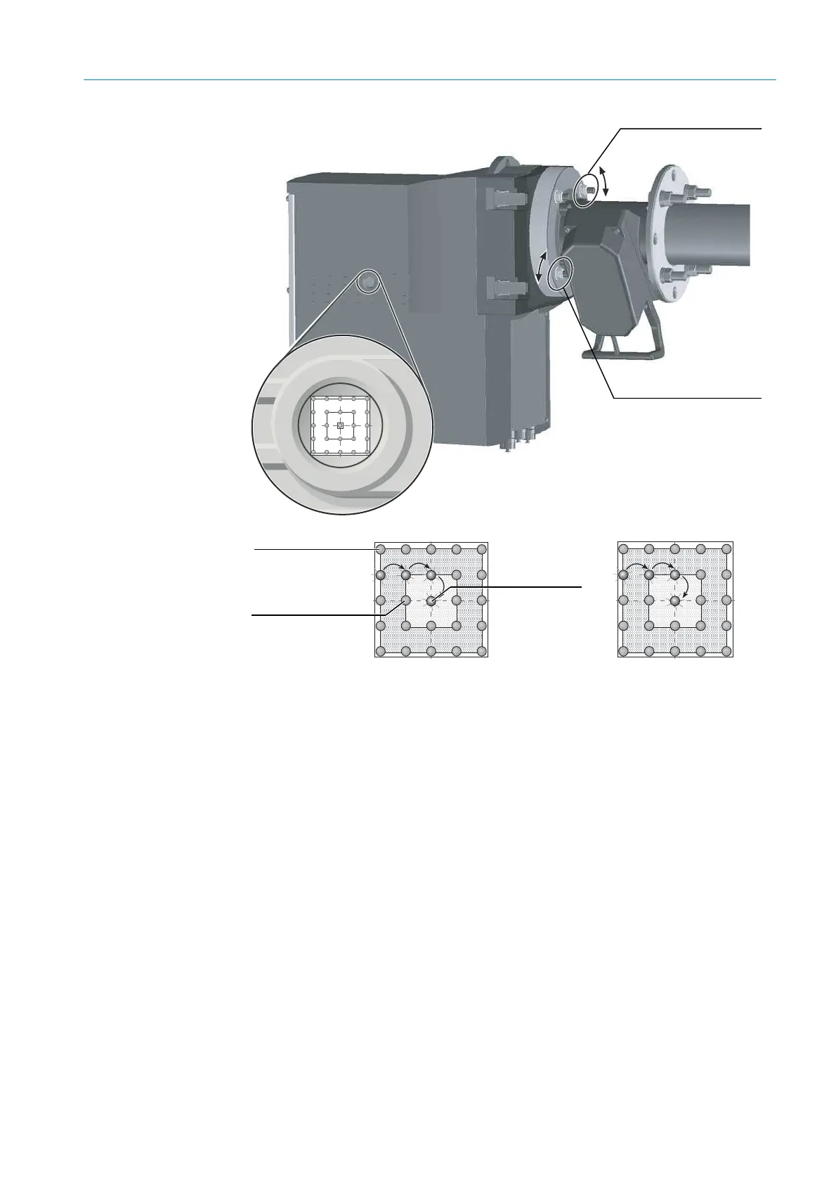
Fig. 53: Aligning the optical axis
Visor The visor indicates the alignment of the optical axis between the SR-unit and the reflector
in the probe using a 5 x 5 LED matrix. The LEDs light up to represent the position of the
light beam on the reflector at the probe end. The cross hairs show three fields for aligning
the probe.
▸ Adjust the optical alignment as shown in
“Aligning the optical axis” by adjusting two
screws on the device flange with a 19 mm wrench whilst observing the light position of
the LED at the same time.
Horizontal probe adjustment causes the light spot to shift horizontally on the visor and
vertical adjustment causes a vertical shift. Alignment is correct when the lit LED is
located within the valid field within the cross hairs, or is completely within the inner ring
marking of the cross hairs.
Probe adjustment,
horizontal
Probe adjustment,
vertical
Outside the valid
field
Optimum
alignment
Valid field