1
Ethernet (host port)
2
Serial host interface
3
Switch
4
CAN controller
5
CAN device
6
Device number
7
CAN etc.
8
Branch line
9
Connecting cable permanently connected with the device (male connector, M12, 17-pin,
A-coded)
ß
Device number (GN)
à
Maximum 32 users
á
Example of alternative connection module CDM420-0006
An adapter cable with female connector, M12, 17-pin, A-coded and male connector,
D-Sub-HD, 15-pin is required to connect the device.
NOTE
Activate the CAN data interface in the device using a configuration software, e.g.,
SOPASET.
Configure further settings in the device according to the function of the device in the
system configuration.
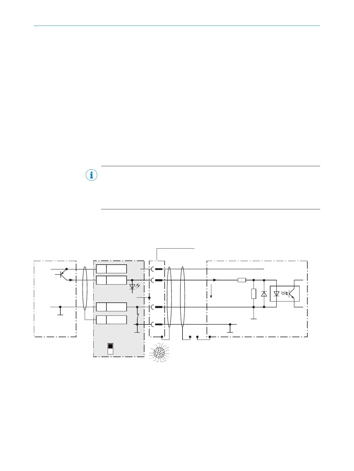
13.3.6 Wiring digital inputs of the device in the CDB650-204
Device = Lector61x = V2D61xx- xxxxxEx
Device 4CDB650-204
PNP sensor 7
V
S
V
S
V
S
GND
SensGND
52.3 K
3 K
Sensor D
V
in
9
C
2
1
12
SGND
6
Shield
11
U
IN
*
A
Out
U
IN
*
GND
S3
Trigger sensor 1
E.g. photo-electric
switch 6
ON
OFF
S3 : SGND-GND
Shield
GND
.
.
.
SensGND
GND
3
1
7
2
6
5
4
8
13
14
17
15
9
10
12
16
11
5
SENS/IN B
3
8
Cable 2
Figure 34: Trigger sensor supplied with power by connection module CDB650-204.
ANNEX 13
8024830/1MBT/2024-05-22 | SICK O P E R A T I N G I N S T R U C T I O N S | Lector61x
67
Subject to change without notice