Wiring digital inputs via connection module
Connection modules Digital inputs Reference
CDB650-204 SENS/IN 1
SENS/IN 2
see "Wiring digital inputs of
the device in the CDB650-204",
page 67
CDM420-0006 Sensor 1
Sensor 2
see "Wiring digital inputs of the
device in the CDM420-0006",
page 76
6.5.6 Wiring the digital outputs
The digital outputs Result 1 to Result 3 are used to signal events in the read operation.
Different functions can be assigned to the digital outputs independently of each other
for this purpose. If the assigned event occurs, then the corresponding digital output
becomes live after the end of the read cycle for the selected pulse duration, for
example (default).
Positions of digital outputs:
•
Male connector of the device cable (M12, 17-pin, A-coded)
•
Open end of the adapter cable (female connector, M12, 17-pin, A-coded/open
end)
•
CDB650-204 connection module
All digital outputs are each available at the individual positions.
The three digital outputs are available in the CDM420-0006 connection module but
reduced to two outputs (“Result1“ “Result2“). Connect the device to the CDM420-0006
connection module using an adapter cable (female connector, M12, 17-pin, A-
coded/male connector, D-Sub-HD, 15-pin).
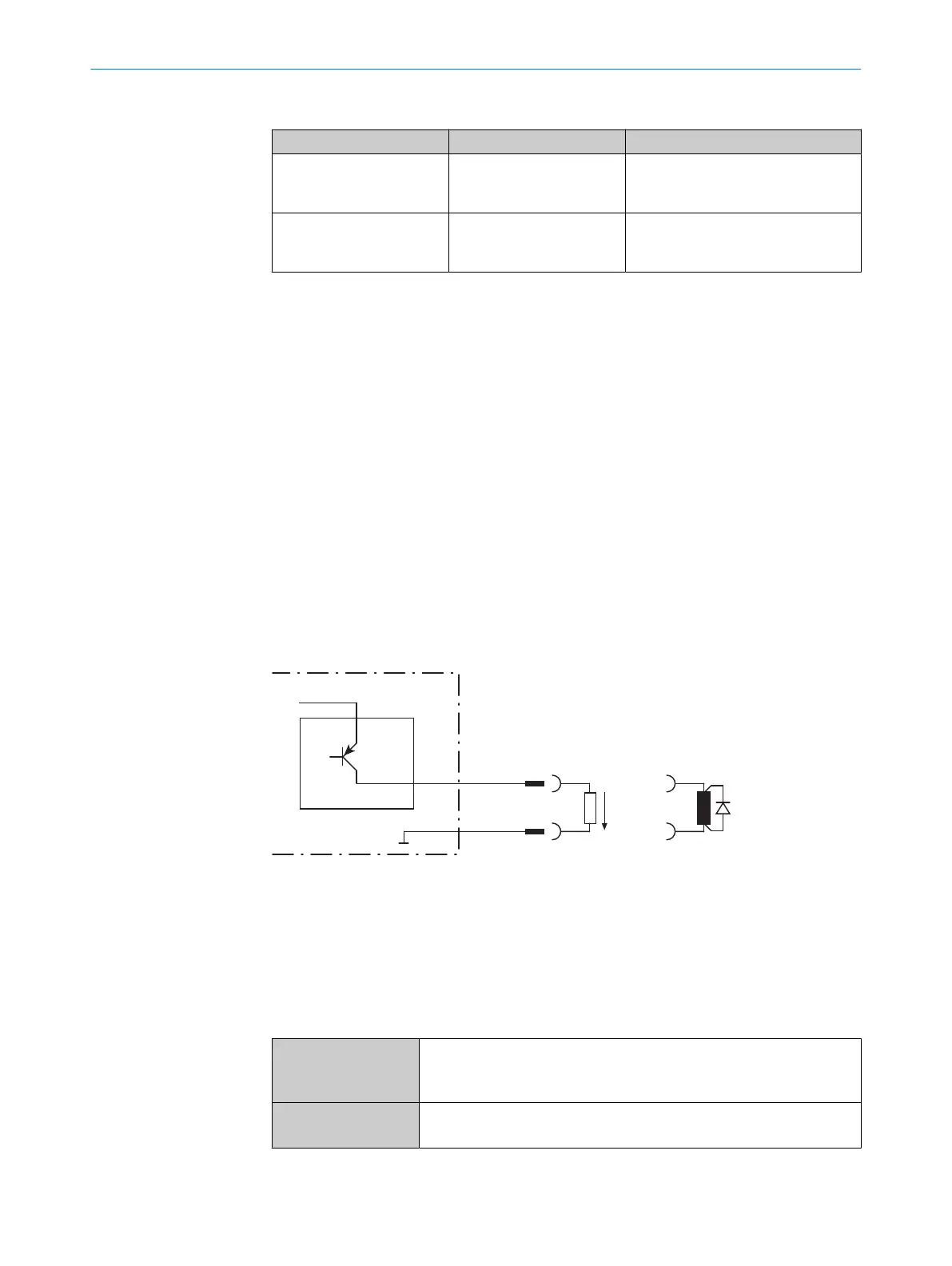
V
out
3
4
Switching output of device 1
!
"
Signal 2
GND
Figure 22: Wiring a digital output
1
Digital output of the device (Result 1 to Result 3)
2
Output signal
3
Output voltage V
out
4
With inductive load: see note
!... "
For pin assignment, see respective device
Table 10: Characteristic data of the digital outputs
Switching behavior PNP switching to supply voltage V
S
Default: No function
Logic: not inverted (active high)
Properties
•
Short-circuit protected
•
Not electrically isolated from V
S
1)
6 ELECTRICAL INSTALLATION
40
O P E R A T I N G I N S T R U C T I O N S | Lector61x 8024830/1MBT/2024-05-22 | SICK
Subject to change without notice