U
System
Controller
Power Supply
SICK
Device
8 6
5
21 3
4
7
= 9
= ß
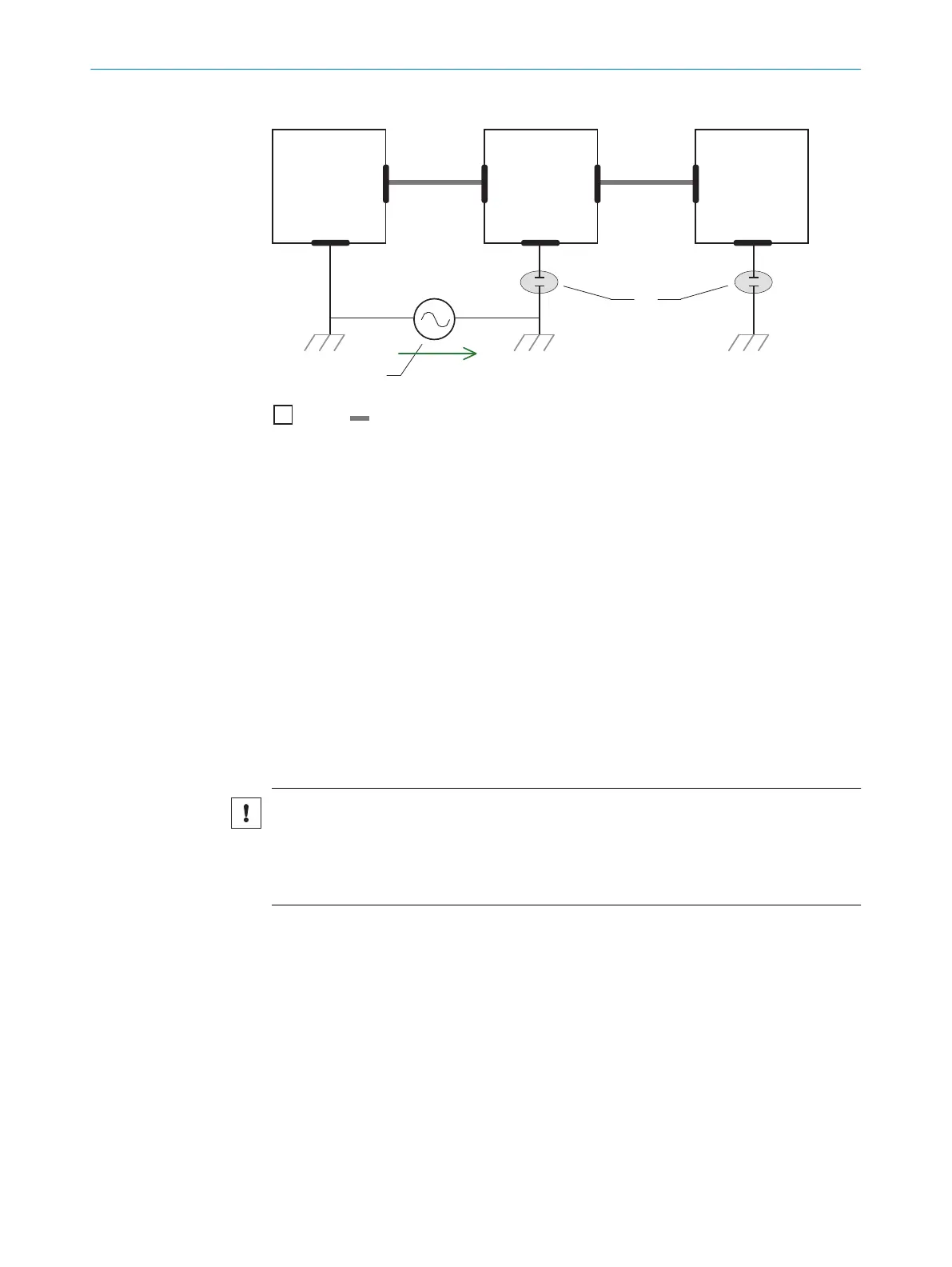
Figure 14: Example: Prevention of equipotential bonding currents in the system configuration by
the insulated mounting of the device
1
System controller
2
Device
3
Voltage supply
4
Grounding point 3
5
Insulated mounting
6
Grounding point 2
7
Ground potential difference
8
Grounding point 1
9
Metal housing
ß
Shielded electrical cable
Even in the event of large differences in the ground potential, ground loops are effec‐
tively prevented. As a result, equalizing currents can no longer flow via the cable shields
and metal housing.
NOTICE
The voltage supply for the device and the connected peripheral devices must also
guarantee the required level of insulation.
Under certain circumstances, a tangible potential can develop between the insulated
metal housings and the local ground potential.
6.3 Connection diagrams
6.3.1 Service mode connection schematic
This operating mode is recommended for initial commissioning of the product.
ELECTRICAL INSTALLATION 6
8024830/1MBT/2024-05-22 | SICK O P E R A T I N G I N S T R U C T I O N S | Lector61x
31
Subject to change without notice