Lector61x
Connection module 2
Configuration
Image display
Diagnostics
SOPASSOPAS
"Power/Serial Data/
CAN/I/O"
(Host)
...
...
1
2
V
S
1
GND
Computer
"Ethernet" (AUX,
image transfer) 3
V
S
EthernetEthernet
Cable 6
5
Cable 4
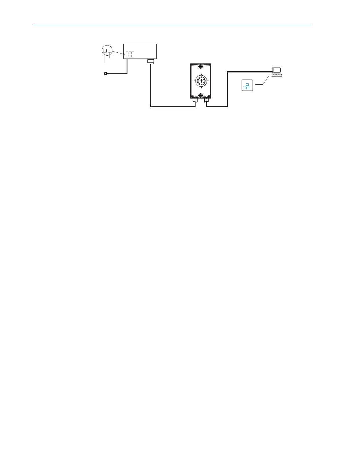
Figure 15: Connection block diagram for commissioning
1
Supply voltage V
S
2
Connection module CDB650-204 or CDM420-0006
3
Ethernet, AUX interface (image transmission)
4
Adapter cable (male connector, M12, 4-pin, D-coded/male connector, RJ-45, 8-pin)
5
Configuration with SOPAS ET, image display or reading diagnostics
6
For CDB650-204: Connection cable 1:1 (female connector, M12, 17-pin, A-coded/male
connector, M12, 17-pin, A-coded)
For CDM420-0006: Adapter cable (female connector, M12, 17-pin, A-coded/male con‐
nector, DSub-HD, 15-pin)
6 ELECTRICAL INSTALLATION
32
O P E R A T I N G I N S T R U C T I O N S | Lector61x 8024830/1MBT/2024-05-22 | SICK
Subject to change without notice