Term CAN
Term 485RS
SGND - GND
422 485
ONOFF
NO
YES
ONOFF
ONOFF
S2 S3
S7S6
S4
CMC
ONOFF
POWER
S1
30 31 32 33 34
CAN_H
CAN_L
T+
R+
GND
40 41 42 43 44
CAN_H
CAN_L
T‒/TxD
R‒/RxD
GND
AUX interface
U
IN
U
IN
GND
GND
Shield
Shield
Shield
Shield
1 2 3 4 5 6 7 8
LEDs
V
S
V
S
Out
GND
Result 1 3
- e.g. PLC 2
GND
Result 2 3
Result 3 3
- Device 6
Pin
2: RxD
3: TxD
5: GND
Host
TxD
RxD
GND
2 A T
F
SENSOR
50 51 52 53 54
RES/
OUT 3
RES/
OUT 4
Ext. Illum.
TR
L+
GND
20 21 22 23 24
GND
RES/
OUT 1
RES/
OUT 2
EXT.
OUT 1
EXT.
OUT 2
10 11 12 13 14 15 16 17 18
U
IN
*
U
IN
*
SGND
SGND
SGND
EXT.
IN 1
SENS/
IN 1
SENS/
IN 2
EXT.
IN 2
3
1
7
2
6
5
4
8
13
14
17
15
9
10
12
16
11
5
1
CDB650-204
V
S
- U
IN
-
F
S 1
- U
IN
*
4
7
RS-232
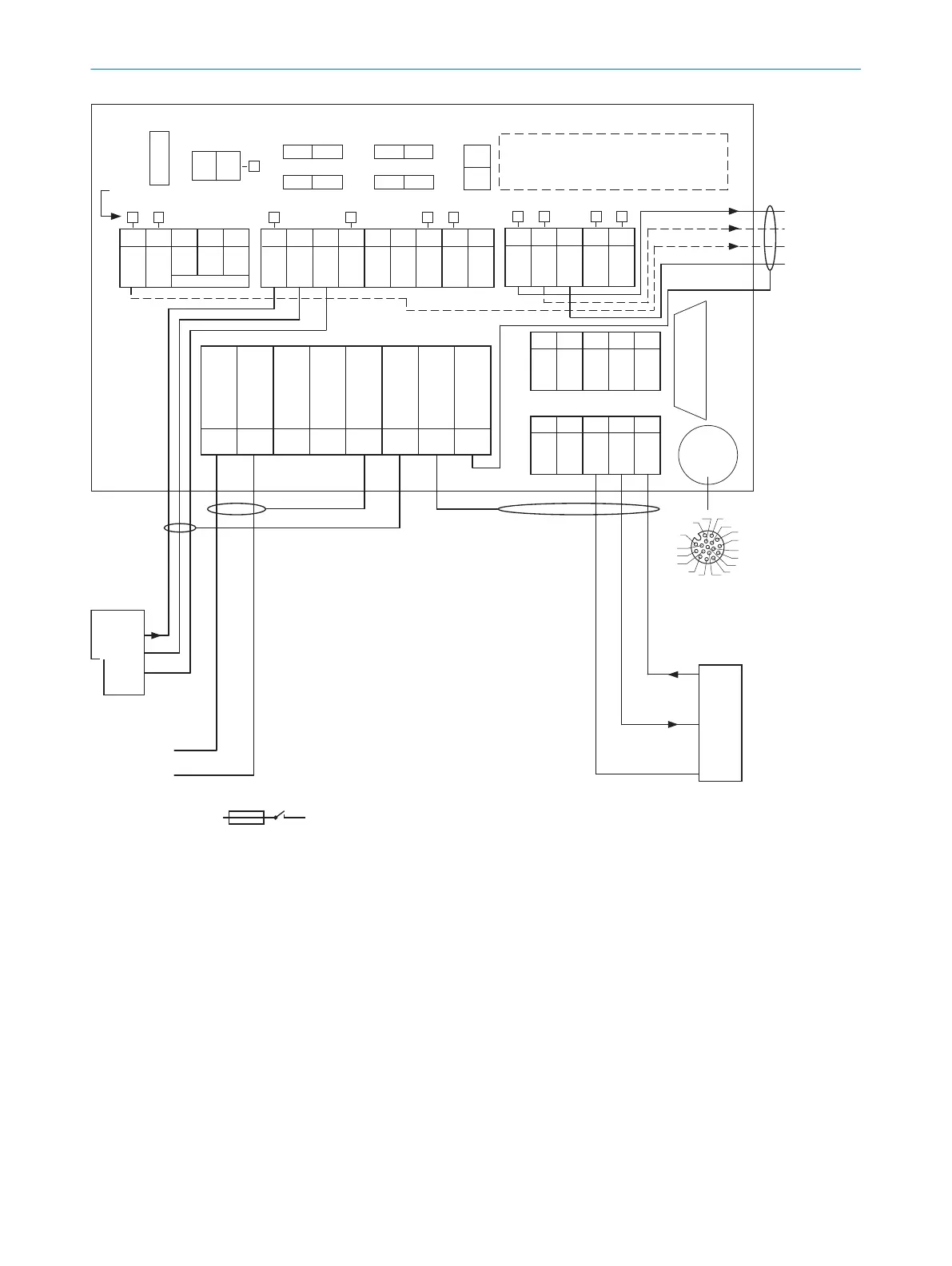
Figure 30: Connection of device and peripherals to the CDB650-204 connection module (overview).
1
External trigger sensor
2
E.g., PLC (programmable logic controller)
3
Name of the digital output
4
SENSOR = Device
5
Female connector, M12, 17-pin, A-coded
6
Device to be connected
7
Supply voltage V
S
13.3.3 Connecting supply voltage for the device in CDB650-204
Device = Lector61x = V2D61xx- xxxxxEx
ANNEX 13
8024830/1MBT/2024-05-22 | SICK O P E R A T I N G I N S T R U C T I O N S | Lector61x
63
Subject to change without notice