1
External trigger sensor
2
Supply voltage V
S
3
Name of the digital output
4
E.g., PLC (programmable logic controller)
5
SCANNER = Device
6
Female connector, D-Sub-HD, 15-pin
7
Device to be connected
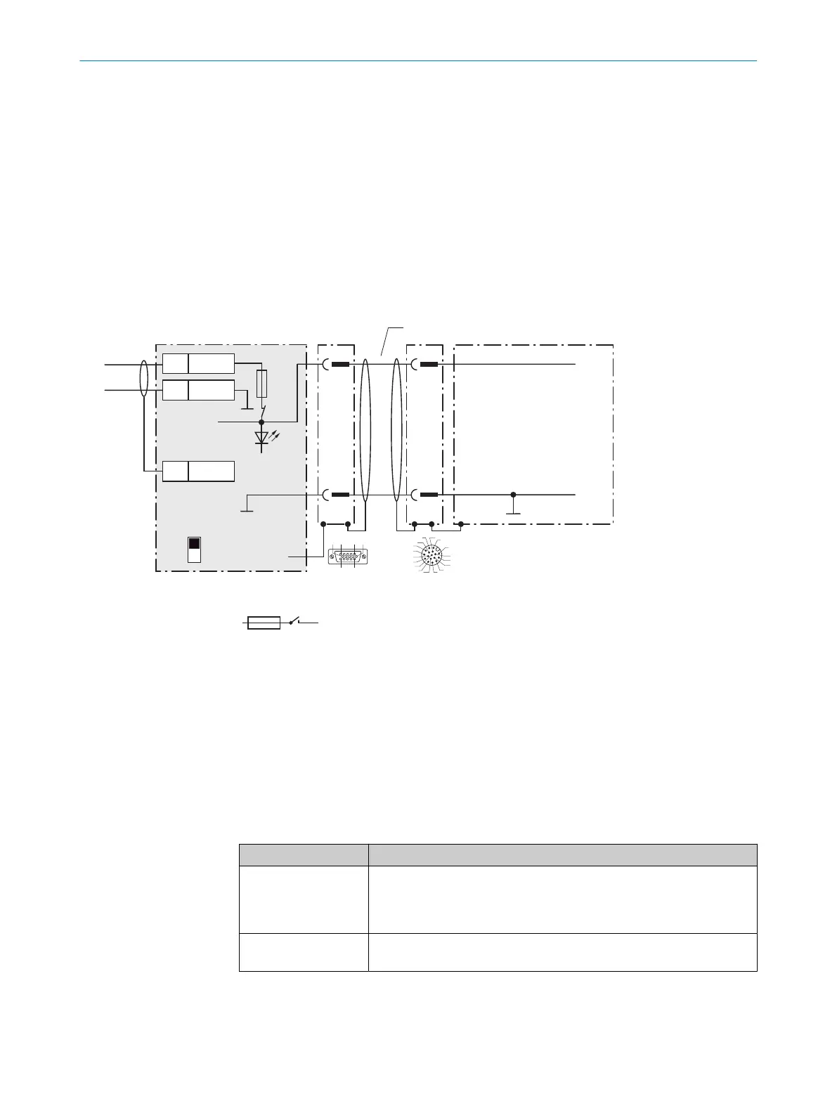
13.4.3 Connecting supply voltage for the device in CDM420-0006
Device = Lector61x = V2D61xx-xxxxxEx
Device
3CDM420-0006
V
S
2
1
1
5
5
Shield
1 +24 V
2 GND
+24 V*
GND
S1
F
Shield
GND
.
.
.
.
.
.
.
.
.
ON
OFF
S1 : POWER
+24 V*
POWER
V
S
GND
3
1
7
2
6
5
4
8
13
14
17
15
9
10
12
16
11
V
S
- +24 V -
F
S 1
- +24 V*
5 4
Cable 2
V
s
1
110
15
6
11
5
Figure 39: Connecting supply voltage for the device in CDM420-0006 connection module.
1
Supply voltage V
S
2
Adapter cable with male connector, D-Sub-HD, 15-pin and female connector, M12, 17-pin, A-coded
3
Device
4
Connecting cable with male connector, M12, 17-pin, A-coded permanently connected with the device
5
Connection module: female connector, D-Sub-HD, 15-pin
Function of switch S1
Table 27: Switch S1: Power
Switch setting Function
ON Supply voltage +24V connected to CDM420-0006 and device via fuse
as +24V* supply voltage
Supply voltage +24V* can be additionally tapped at terminals 29 and
39
OFF CDM420-0006 and device disconnected from supply voltage
Recommended setting for all connection work
13.4.4 Wiring serial host interface RS-232 of the device in the CDM420-0006
Device = Lector61x = V2D61xx-xxxxxEx
ANNEX 13
8024830/1MBT/2024-05-22 | SICK O P E R A T I N G I N S T R U C T I O N S | Lector61x
73
Subject to change without notice