6.3.3 Example applications
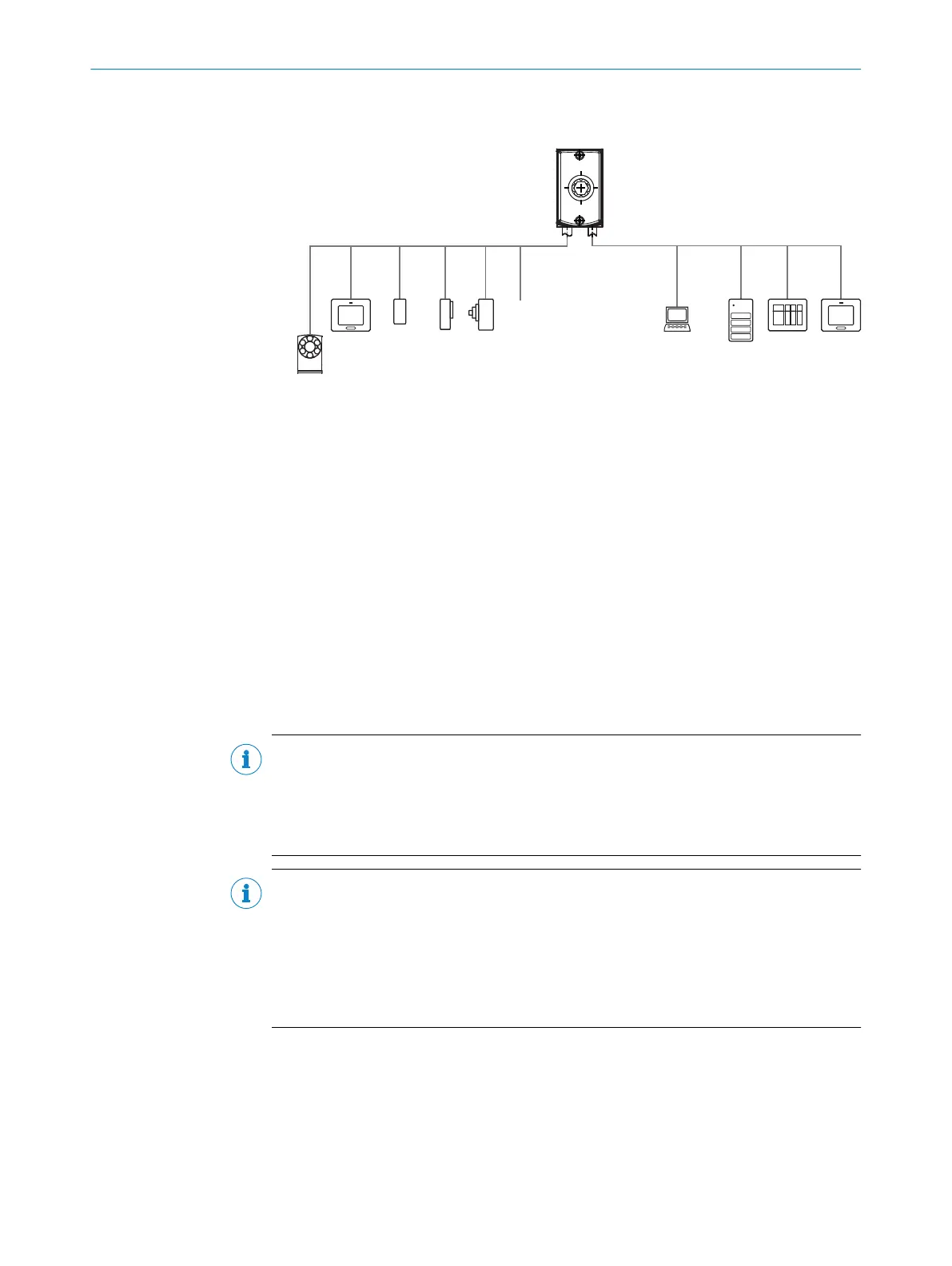
Ethernet
Lector61x
V
S
PC
FTP 9
SOPAS ETSOPAS ET
Configuration 6
Image display 7
Diagnostics 8
HMI ß PLC 3
PLC 3
Digital
inputs 5
Digital
outputs 4
serial 2
EthernetSerial Data (RS-232), CAN, I/O, Power
CSN (CAN sensor
network) 1
Figure 17: Facilities for connecting
1
CSN (CAN sensor network)
2
Serial
3
PLC (programmable logic controller)
4
Digital outputs, e.g. for signal lamps
5
Digital inputs e.g. for encoders, photoelectric sensors (trigger sensor)
6
Configuration
7
Image display
8
Diagnostics
9
FTP server (image storage)
ß
HMI interface
6.4 Pin assignment
Important information
NOTE
Limitations in the options for backing up the parameter set
The device does not come with an AUX serial interface.
A current and application-specific parameter set created in SOPASET can therefore only
be manually saved and archived as a project file on the computer.
NOTE
Using an additional extension cable
•
If the serial interface (RS-232) is not being used, the maximum total length of
cable is 30m.
•
If the serial interface (RS-232) is being used, the maximum total length of cable is
15m.
•
Wire diameter: at least AWG26 (0.14mm
2
).
6 ELECTRICAL INSTALLATION
34
O P E R A T I N G I N S T R U C T I O N S | Lector61x 8024830/1MBT/2024-05-22 | SICK
Subject to change without notice