Power/Serial Data/CAN/I/O
3
1
7
2
6
5
4
8
13
14
17
15
9
10
12
16
11
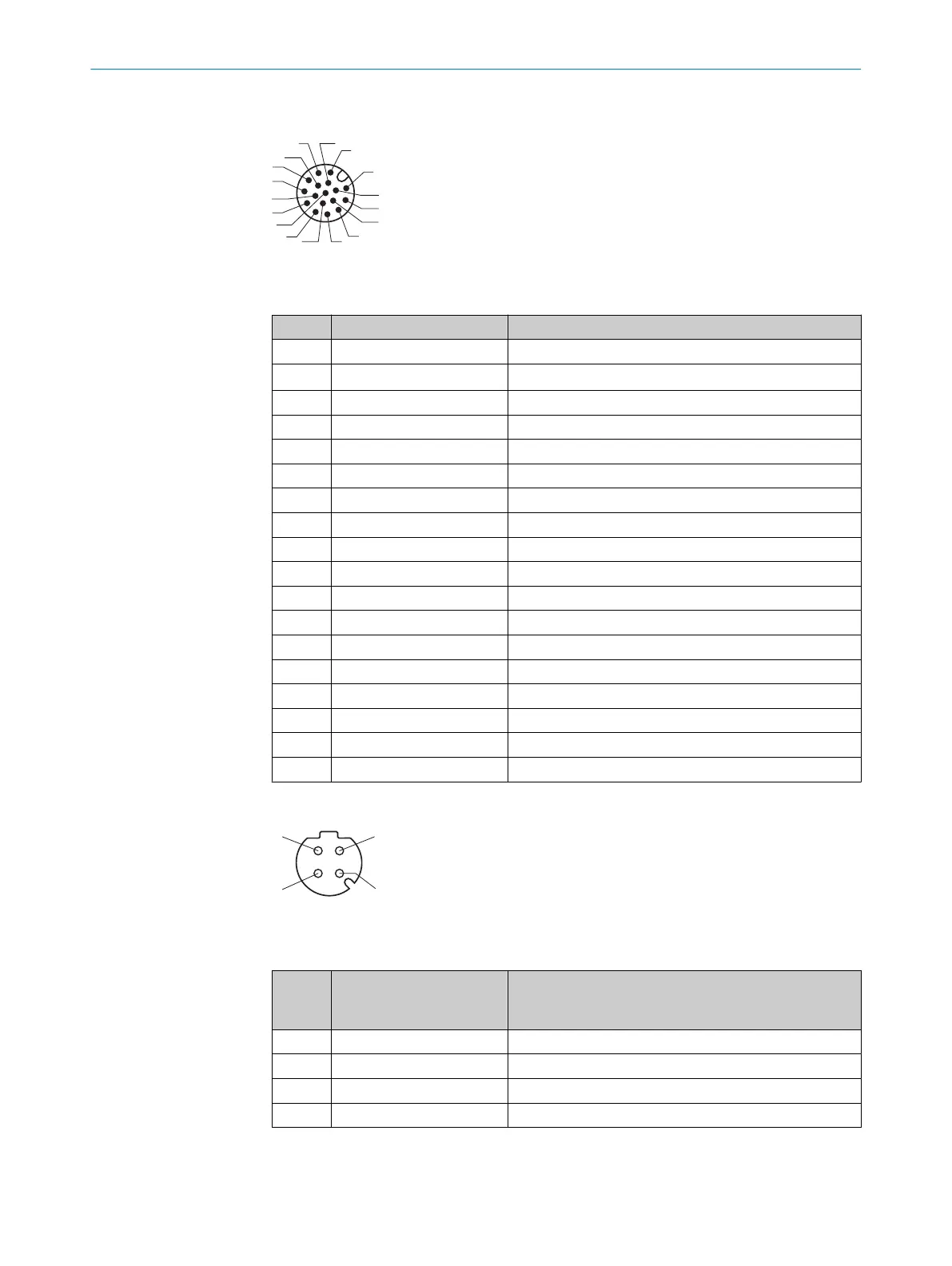
Figure 18: Male connector, M12, 17-pin, A-coded
Table 3: Pin assignment for Power/Serial Data/CAN/I/O
Contact Signal Function
1 GND Ground
2 V
S
Supply voltage
3 CAN L CAN bus (IN/OUT)
4 CAN H CAN bus (IN/OUT)
5 – –
6 TxD (RS-232), host Serial data interface (sender)
7 – –
8 – –
9 SensGND Digital input ground
10 Sensor 1 Digital input 1
11 – –
12 RxD (RS-232), host Serial data interface (receiver)
13 Result 1 Digital output 1
14 Result 2 Digital output 2
15 Sensor 2 Digital input 2
16 Result 3 Digital output 3
17 – –
– – Shield
Ethernet
Figure 19: M12 female connector, 4-pin, D-coded
Table 4: Ethernet pin assignment
Female
connec‐
tor
Signal Function
1 TD+ Sender+
2 RD+ Receiver+
3 TD– Sender–
4 RD– Receiver–
ELECTRICAL INSTALLATION 6
8024830/1MBT/2024-05-22 | SICK O P E R A T I N G I N S T R U C T I O N S | Lector61x
35
Subject to change without notice