NOTICE
Risk of damage to the internal interface modules!
If the serial data interfaces are wired incorrectly, then electronic components in the
device could get damaged.
■
Observe the information on wiring.
■
Carefully check the wiring prior to switching on the device.
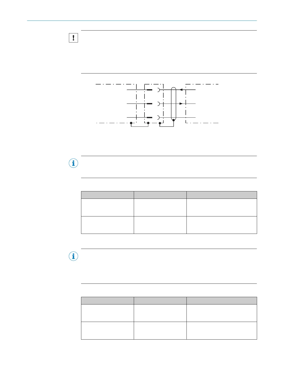
RS-232
2
3
4
Device 1 Host
TxD
RxD
GND
RxD
TxD
GND
Figure 20: Wiring of the RS-232 serial data interface
1
Device
2...4
Pin assignment: see RS-232 pin assignment for the respective device
NOTE
Activate the serial data interface type in the device using a configuration software, e.g.,
the SOPASET configuration software.
Wiring data interfaces via a connection module
Connection modules Data interface Reference
CDB650-204 RS-232 see "Wiring serial host inter‐
face RS-232 of the device in
CDB650-204", page 64
CDM420-0006 RS-232 see "Wiring serial host interface
RS-232 of the device in the
CDM420-0006", page 73
6.5.4 Wiring the CAN interface
NOTE
Activate the CAN data interface in the device using a configuration software, e.g.,
SOPASET.
Configure further settings in the device according to the function of the device in the
system configuration.
Wiring CAN interfaces via a connection module
Connection modules Interface Reference
CDB650-204 CAN see "Wiring the CAN interface of
the device in the CDB650-204",
page 65
CDM420-0006 CAN see "Wiring the CAN interface of
the device in the CDM420-0006",
page 74
6 ELECTRICAL INSTALLATION
38
O P E R A T I N G I N S T R U C T I O N S | Lector61x 8024830/1MBT/2024-05-22 | SICK
Subject to change without notice