Device 1 CDM420-0006 Host
5
.
.
.
TxD
RxD
RxD
TxD
GND
GND
GND
12
1
9
7
6
34
T‒/TxD
35
R‒/RxD
36
GND
6
Shield
RS-232 RS-232
ON
OFF
S2 : RS 485
ON
OFF
S3: Term 422
S2
OFFON
2
3
1
7
2
6
5
4
8
13
14
17
15
9
10
12
16
11
110
15
6
11
5
4 3
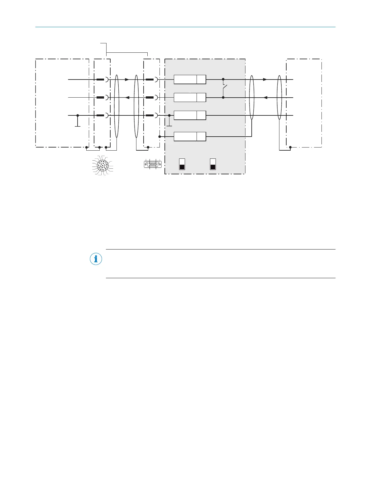
Figure 40: Wiring data interface RS-232 of the device in connection module CDM420-0006.
1
Device
2
Adapter cable with male connector, D-Sub-HD, 15-pin and female connector, M12, 17-pin, A-coded
3
Connection module: female connector, D-Sub-HD, 15-pin
4
Connecting cable permanently connected with the device (male connector, M12, 17-pin, A-coded)
NOTE
Activate the RS-232 data interface in the device using a configuration software, e.g.,
SOPASET.
13.4.5 Wiring the CAN interface of the device in the CDM420-0006
Device = Lector61x = V2D61xx-xxxxxEx
Not considered: connection and looping through of the supply voltage, connection of a trigger sensor for read cycle
generation (e.g. at the CAN controller)
13 ANNEX
74
O P E R A T I N G I N S T R U C T I O N S | Lector61x 8024830/1MBT/2024-05-22 | SICK
Subject to change without notice