“V
S
”
“Host 2”
“Result 2”
“Result 3”
“Result 1”
“CAN”
“Sensor 2”
“Sensor 1”
“AUX”
CAN bus
“Result 1”
“Result 2”
PLC
“Result 3”
CDB650-204
Connection module 5
“Host 2”
HOST/PLC
Further data
processing 7
Computer
Configuration
Diagnostics
Image display
Interfaces 3
Device 2
“Ethernet” (Host 1/Aux), Image transfer 4
RS-232
Ethernet
“Host 1”
Ethernet
“Aux”
“Sensor 2”
“Sensor 1”
1
V
S
8
9
6
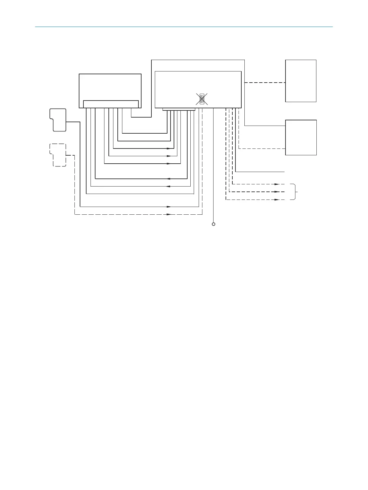
Figure 29: Connection of the device to peripherals via CDB650-204 (overview)
1
External trigger sensor
2
Device
3
Interfaces
4
Image transmission
5
Connection modules
6
Configuration, diagnostics or image display
7
Data further processing
8
Supply voltage V
S
9
Can also be used as an alternative stop trigger (e.g., photoelectric sensor) or travel increment (incremental encoder),
depending on the application
13.3.2 Wiring overview of the CDB650-204
Device = Lector61x = V2D61xx-xxxxxEx, 1 digital input used
13 ANNEX
62
O P E R A T I N G I N S T R U C T I O N S | Lector61x 8024830/1MBT/2024-05-22 | SICK
Subject to change without notice