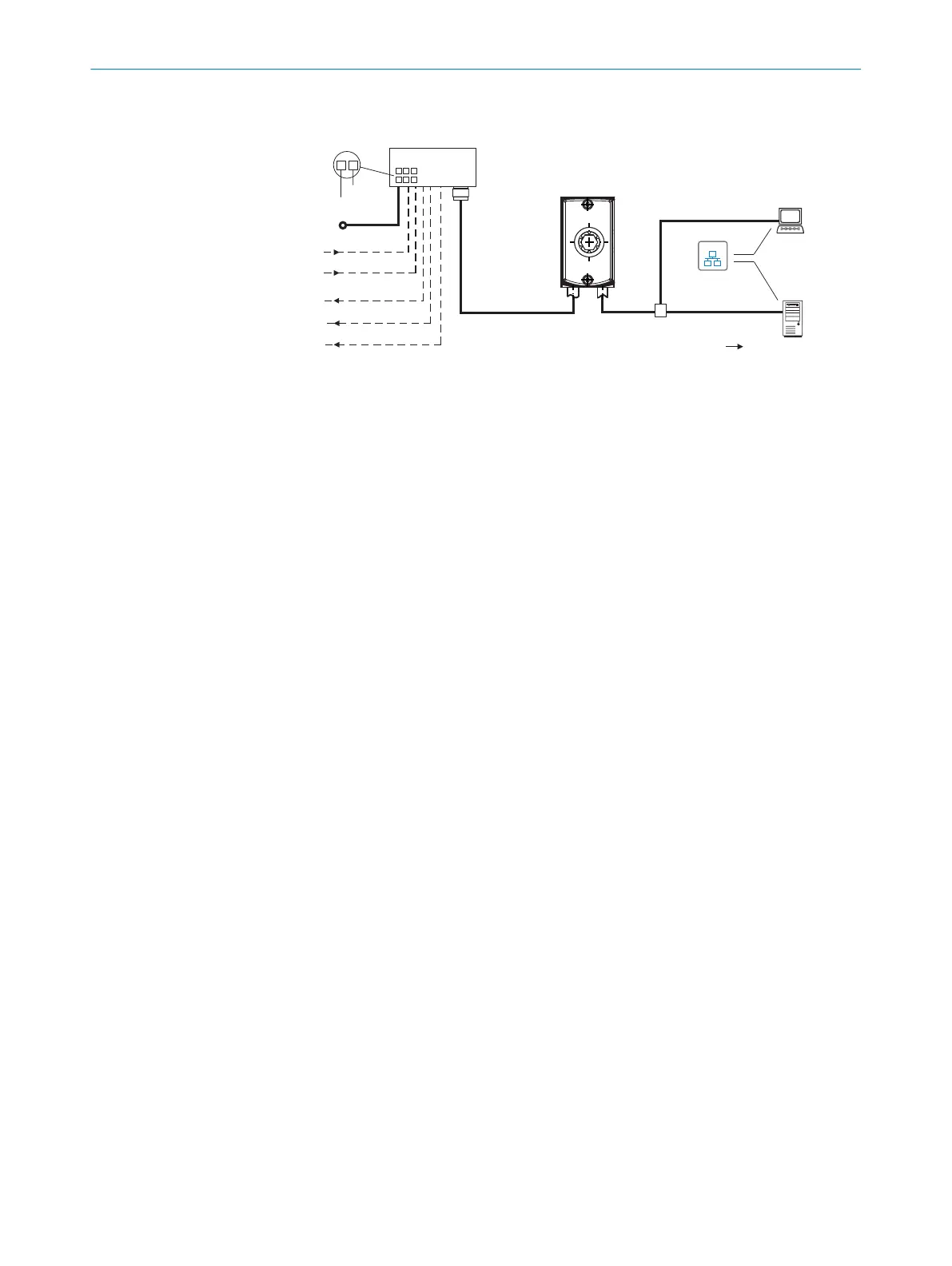
6.3.2 Connection principle for read mode
"Ethernet"
(Host)
Input 2 à
Input 1 á
Output 1 ß
Output 2 9
Output 3 8
Lector61x
Connection module 2
Image display
SOPASSOPAS
"Power/Serial Data/
CAN/I/O"
(Host)
...
...
1
2
V
S
1
GND
HOST
Computer
Further data
processing
"Ethernet" (AUX,
image transfer) 3
V
S
EthernetEthernet
Cable 7
4
6
Reading result 5
Figure 16: Connection block diagram for read mode
1
Supply voltage V
S
2
Connection module CDB650-204 or CDM420-0006
3
Ethernet, AUX interface (image transmission)
4
Image display
5
Read result
6
Data further processing
7
For CDB650-204: Connection cable 1:1 (female connector, M12, 17-pin, A-coded/male
connector, M12, 17-pin, A-coded)
For CDM420-0006: Adapter cable (female connector, M12, 17-pin, A-coded/male con‐
nector, DSub-HD, 15-pin)
8
Digital output 3, e.g. for connecting an LED
9
Digital output 2, e.g. for connecting an LED
ß
Digital output 1, e.g. for connecting an LED
à
Digital input 2, e.g. for connecting an incremental encoder
á
Digital input 1, e.g. for connecting a read cycle trigger sensor
ELECTRICAL INSTALLATION 6
8024830/1MBT/2024-05-22 | SICK O P E R A T I N G I N S T R U C T I O N S | Lector61x
33
Subject to change without notice