Protecting the supply cables
To ensure protection against short-circuits/overload in the customer’s supply cables,
appropriately choose and protect the wire cross-sections used.
Observe applicable standards (Germany):
•
DIN VDE 0100 (part 430)
•
DIN VDE 0298 (part 4) and DIN VDE 0891 (part 1)
Connecting device without connection module
For a supply voltage of DC 12V to 24V ±15%, protect the device with a separate 2A
fuse.
►
Install the fuse in the supply circuit at the start of the supply cable.
Connecting device with connection module
The supply voltage for the device is protected as follows in the connection modules in
the circuit after switch S1:
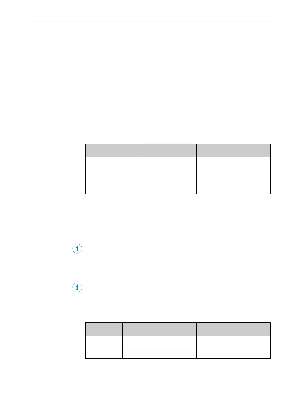
Table 7: Protection of the supply voltage in the connection module
Connection modules Supply voltage fuse protec‐
tion
Reference
CDB650-204 2A (slow-blow) see "Connecting supply voltage
for the device in CDB650-204",
page 63
CDM420-0006 2A (slow-blow) see "Connecting supply voltage
for the device in CDM420-0006",
page 73
6.5.3 Wiring the data interface
Wiring the Internet interface
1. Connect the device to the Ethernet connection of the computer via the adapter
cable.
2. Set up communication via the SOPASET configuration software.
NOTE
The Ethernet interface of the device has an Auto-MDIX function. This automatically
adjusts the transmission speed as well as any necessary crossover connections.
Wiring the serial data interface
NOTE
The serial data interface is available only as a host interface for this device.
The maximum data transmission rate for the serial interface depends on the length of
cable and on the type of interface.
Table 8: Data transmission rates and recommended maximum lengths of cable
Interface Data transmission rate Distance to the target computer
(host)
RS-232 Up to 19.2kBd Max. 15m
38.4kBd ... 57.6kBd Max. 5m
115.2kBd … 500kBd <2m
ELECTRICAL INSTALLATION 6
8024830/1MBT/2024-05-22 | SICK O P E R A T I N G I N S T R U C T I O N S | Lector61x
37
Subject to change without notice