Chapter 4 Operating Instructions
M4000 Adv., Adv. A/P, Area
24 © SICK AG • Industrial Safety Systems • Germany • All rights reserved 8010797/PA53/27-06-05
Configurable functions
The connection can signal one of the following states:
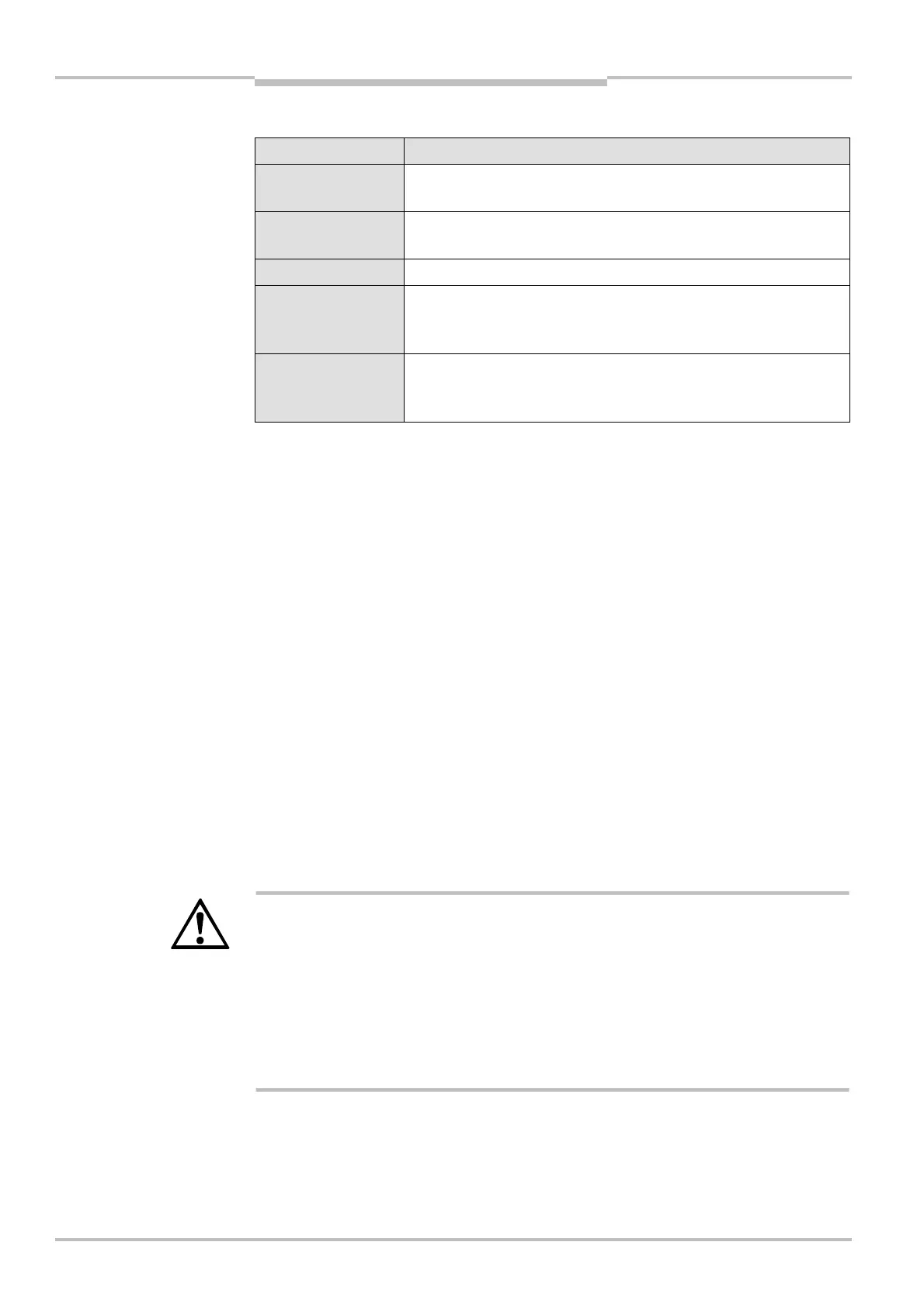
Assignment Possible uses
Contamination
(OWS)
Eases diagnostics in case of contaminated front screen
OSSD status Signals the status of the output signal switching devices when the
multiple light beam safety device switches to red or green
Reset required Signals the status “Reset required”
Muting status Signals the status “Muting”
(only M4000 Advanced and M4000 Advanced A/P in conjunction
with external switching amplifier, e.g. UE403)
Override status Signals the status “Override”
(only M4000 Advanced and M4000 Advanced A/P in conjunction
with external switching amplifier, e.g. UE403)
The electrical connection of a PLC to the application diagnostic output is described in
chapter 6.6 “Application diagnostic output (ADO)” on page 49.
• When you connect the application diagnostic output as an alarm signal for
contamination (OWS) or for the OSSD status, then during the configuration you can
choose how the application diagnostic output is to signal the alarm.
– HIGH active: If there is contamination or if the OSSDs are switched on, 24 V are
present. Otherwise the output is high resistance.
– LOW active: If there is contamination or if the OSSDs are switched on, the output is
high resistance. Otherwise 24 V are present.
• If you use the application diagnostic output as an alarm signal for “Reset required”, it
has a frequency of 1 Hz.
• If you connect the application diagnostic output as an alarm signal for muting or
override status, then the application diagnostic output will always signal the alarm with
an active HIGH. With muting or override 24 V are present. Otherwise the output is high
resistance.
Device symbol M4000 Advanced (receiver), M4000 Advanced (A/P) or M4000 Area
(receiver), context menu Open device window, parameter node General.
4.4 Scanning range
WARNING
Configure the scanning range to suit the dimension of the light path between sender
and receiver!
You must adjust the scanning range of every system to the dimension of the light path
between sender and receiver.
• If the scanning range is set too low, the multiple light beam safety device may not
switch to green.
• If the scanning range is set too large, the multiple light beam safety device may
malfunction due to reflections. This would mean that the operator is at risk.
configuration for the
application diagnostic output
Notes
AUDIN - 7 bis rue de Tinqueux - 51100 Reims - France - Tel : 03.26.04.20.21 - Fax : 03.26.04.28.20 - Web : http: www.audin.fr - Email : info@audin.fr

 Loading...


