Chapter 11 Operating Instructions
M4000 Adv., Adv. A/P, Area
80 © SICK AG • Industrial Safety Systems • Germany • All rights reserved 8010797/PA53/27-06-05
Technical specifications
11.3 Dimensional drawings
11.3.1 M4000 Advanced, M4000 Advanced A/P
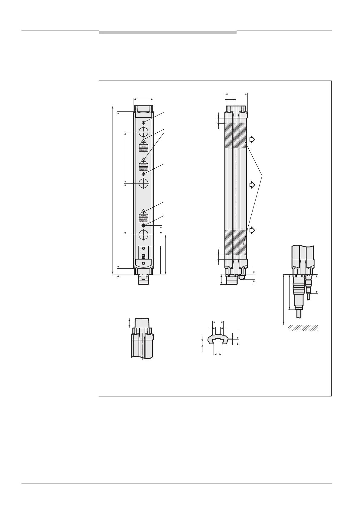
Fig. 48: Dimensional drawing
M4000 Advanced receiver
(sender mirror image) or
M4000 Advanced A/P (mm)
(receiver with
integrated alignment
aid only)
Laser output opening
(receiver with
integrated alignment
aid only)
Optional (receiver only):
Design with integrated
LED
Sliding nut groove for
side mounting
Cable socket M26 with crimp
contacts (for DIN 43
651, left)
and cable plug M12 with
cable (right, only on receiver)
87
47.5
Mounting ranges for
brackets
M4000 Advanced (receiver) or
M4000 Advanced A/P
AUDIN - 7 bis rue de Tinqueux - 51100 Reims - France - Tel : 03.26.04.20.21 - Fax : 03.26.04.28.20 - Web : http: www.audin.fr - Email : info@audin.fr

 Loading...


