Operating Instructions Chapter 4
M4000 Adv., Adv. A/P, Area
8010797/PA53/27-06-05 © SICK AG • Industrial Safety Systems • Germany • All rights reserved
23
Configurable functions
WARNING
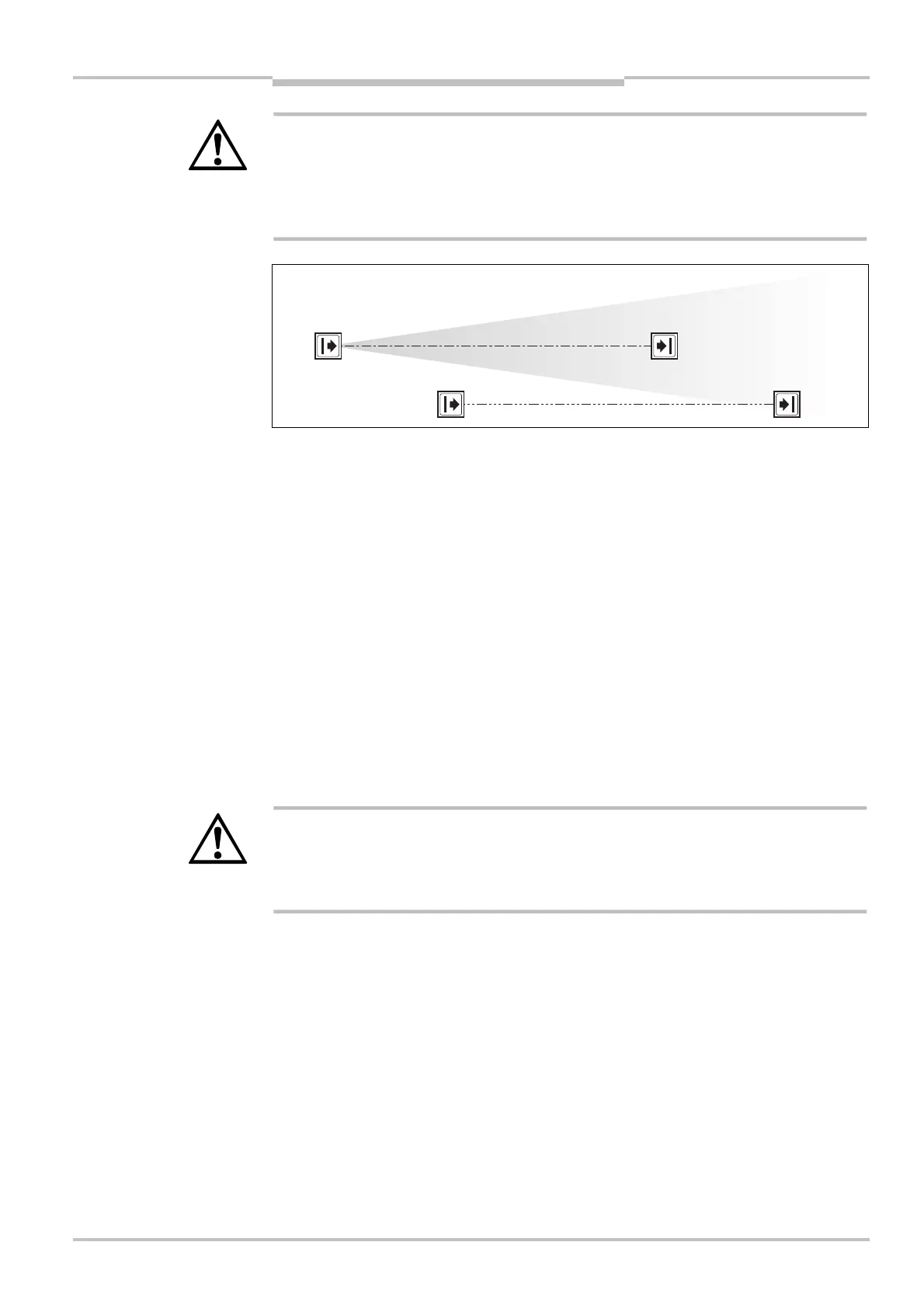
Use different beam codings if the systems are mounted in close proximity!
Systems mounted in close proximity to each other must be operated with different beam
codings (code 1 or code 2). If this precaution is neglected, the system may be impaired in
its protective function by the beams from the neighbouring system and so change to the
unsafe state. This would mean that the operator is at risk.
• Beam coding increases the availability of the protected machine. Beam coding also
enhances the resistance to optical interference such as weld sparks or similar.
• Within a system you must configure the beam coding for every device (sender and
receiver) separately.
• In a cascaded system the host and guest always have the same beam coding. There is
no mutual interference.
• After switching on, the 7@segment display of sender and receiver will briefly display the
coding.
Device symbol M4000 Advanced (sender or receiver), M4000 Advanced (A/P) or M4000
Area (sender or receiver), context menu Open device window, parameter node General.
4.3 Application diagnostic output (ADO)
The M4000 has an application diagnostic output (ADO) that can be configured. With the
aid of the application diagnostic output, the multiple light beam safety device can signal
specific states. You can use this output for a relay or a PLC.
WARNING
You must not use the application diagnostic output for safety-relevant functions!
You are only allowed to use the application diagnostic output for signalling. You must
never use the application diagnostic output for controlling the application or with safety-
relevant functions.
Fig. 15: Schematic
illustration of the beam
coding
Notes
AUDIN - 7 bis rue de Tinqueux - 51100 Reims - France - Tel : 03.26.04.20.21 - Fax : 03.26.04.28.20 - Web : http: www.audin.fr - Email : info@audin.fr

 Loading...


