Chapter 6 Operating Instructions
M4000 Adv., Adv. A/P, Area
50 © SICK AG • Industrial Safety Systems • Germany • All rights reserved 8010797/PA53/27-06-05
Electrical installation
• When you connect the application diagnostic output as an alarm signal for
contamination (OWS) or for the OSSD status, then during the configuration you can
choose how the application diagnostic output is to signal the alarm.
– HIGH active: If there is contamination or if the OSSDs are switched on, 24 V are
present. Otherwise the output is high resistance.
– LOW active: If there is contamination or if the OSSDs are switched on, the output is
high resistance. Otherwise 24 V are present.
• If you use the application diagnostic output as an alarm signal for “Reset required”, it
has a frequency of 1 Hz.
• Only M4000 Advanced and M4000 Advanced A/P in conjunction with external switching
amplifier, e.g. UE403:
If you connect the application diagnostic output as an alarm signal for muting or
override status, then the application diagnostic output will always signal the alarm with
an active HIGH. With muting or override 24 V are present. Otherwise the output is high
resistance.
If you connect the signal output, then you must configure it with the aid of the CDS prior to
commissioning. Details can be found in chapter 4.3 “Application diagnostic output (ADO)”
on page 23.
WARNING
Device configuration after replacement!
If you replace a multiple light beam safety device on which the application diagnostic
output (ADO) is connected and configured, then you must activate the application
diagnostic output (ADO) again via the CDS. It is not enough to only make the electrical
connections.
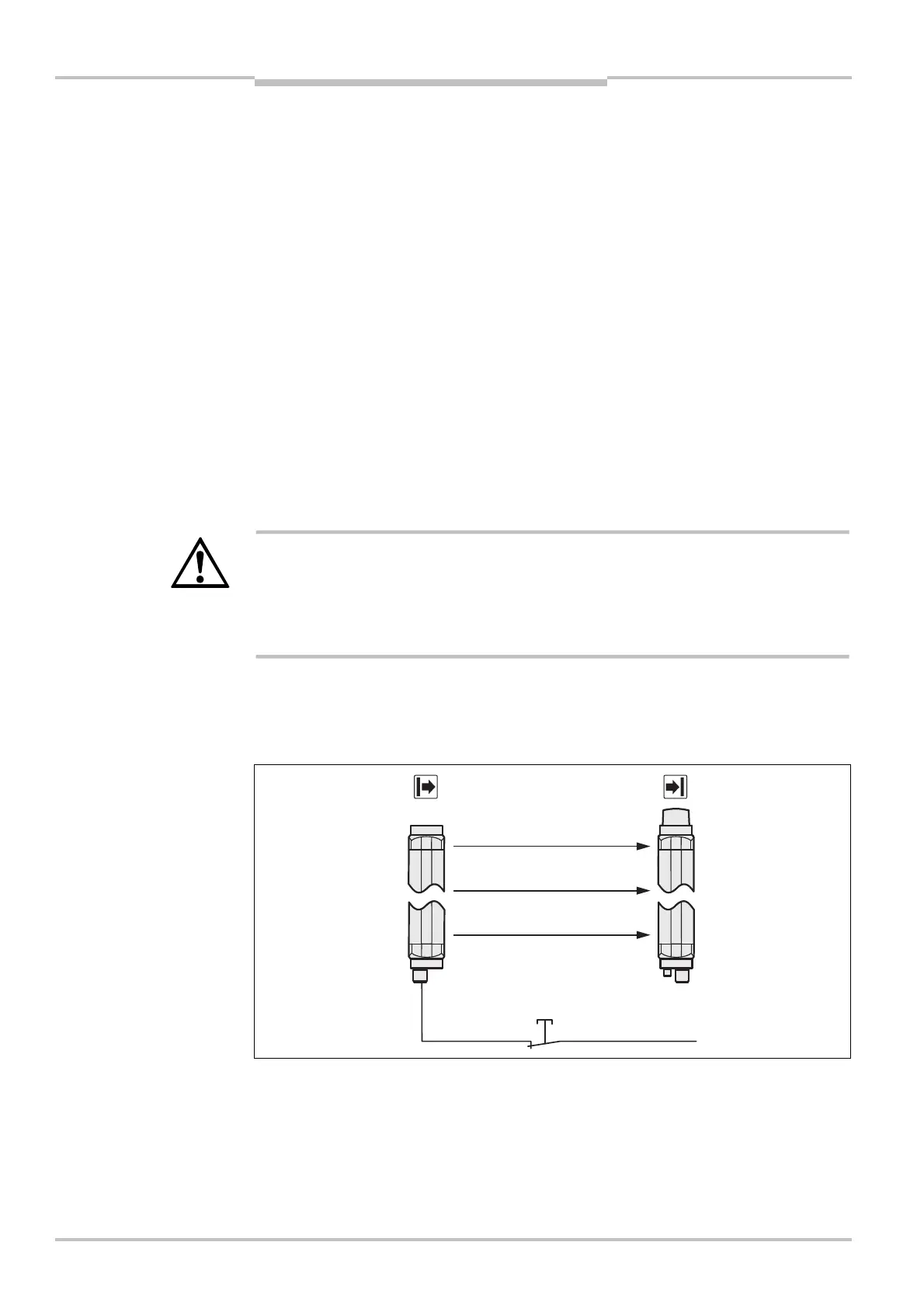
6.7 Test input (sender test)
The function Sender test is not available with the M4000 Advanced A/P.
Notes
Note
Fig. 37: Connection of the
sender test button
AUDIN - 7 bis rue de Tinqueux - 51100 Reims - France - Tel : 03.26.04.20.21 - Fax : 03.26.04.28.20 - Web : http: www.audin.fr - Email : info@audin.fr

 Loading...


