Chapter 6 Operating Instructions
M4000 Adv., Adv. A/P, Area
46 © SICK AG • Industrial Safety Systems • Germany • All rights reserved 8010797/PA53/27-06-05
Electrical installation
Pin Wire colour Sender Receiver
9 Black Device communication (EFI
A
) Device communication (EFI
A
)
10 Purple Device communication (EFI
B
) Device communication (EFI
B
)
11 Grey/pink Input host/guest SEL
2)
Input host/guest SEL
2)
FE Green Functional earth Functional earth
• For the connection of pin 9 and 10 only use cable with twisted cores, e.g. the SICK
connection cables available as accessories (see section 12.7 “Accessories” on
page 98).
• If you do not use either a SICK switching amplifier or a SICK bus node on the system
connection pin 9 and 10 (EFI device communication), to improve the EMC behaviour we
recommend, especially on cascaded systems, the termination of the connections pin 9
and 10 (EFI device communication) on the system connection in the control cabinet
using a resistor of 182 (SICK part number 2027227).
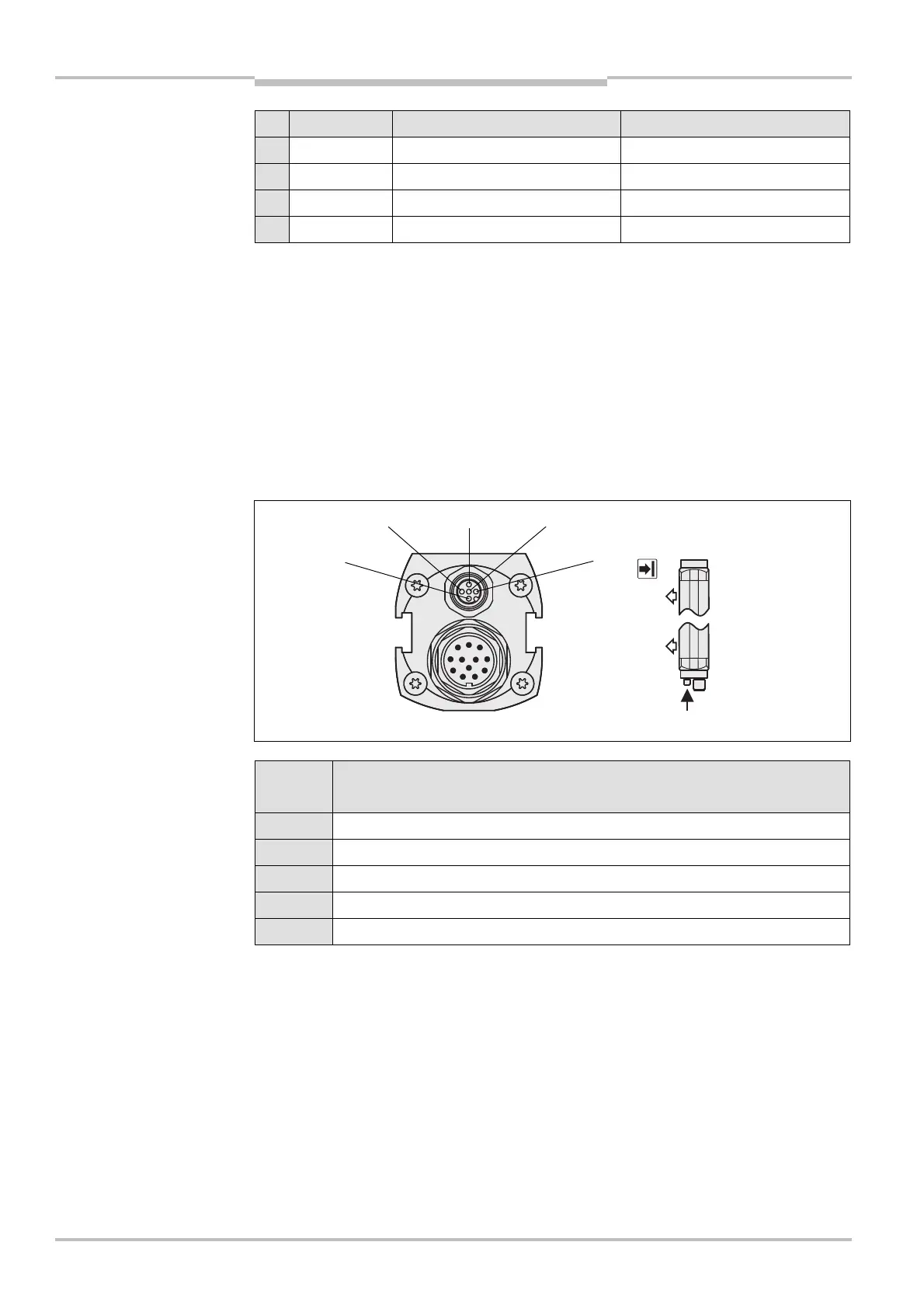
6.2 Extension connection M12× 4 + FE for UE403
Pin M4000 Advanced (receiver) or
M4000 Advanced A/P
1 24 V DC output (voltage supply UE403)
2 Device communication (EFI
A
)
3 0 V DC (voltage supply UE403)
4 Device communication (EFI
B
)
FE Functional earth
2)
Applies only to the M4000 Area 60; on the M4000 Area 80 pin 11 is reserved.
Notes
Fig. 32: Pin assignment
extension connection
M12
× 4 + FE
extension connection
M12
× 4 + FE
AUDIN - 7 bis rue de Tinqueux - 51100 Reims - France - Tel : 03.26.04.20.21 - Fax : 03.26.04.28.20 - Web : http: www.audin.fr - Email : info@audin.fr

 Loading...


