Chapter 3 Operating Instructions
M4000 Adv., Adv. A/P, Area
18 © SICK AG • Industrial Safety Systems • Germany • All rights reserved 8010797/PA53/27-06-05
Product description
• The formation of droplets of heavy contamination can be detrimental to the reflection
behaviour. Take the necessary organisational measures to avoid the formation of
droplets on the deflector mirrors. The deflector mirrors are available as accessories
(see page 88f.).
• Deflector mirrors reduce the effective scanning range. The effective scanning range
depends on the number of deflector mirrors in the light path (see chapter 4.4 “Scanning
range” on page 24ff).
• You can extend the M4000 Advanced A/P multiple light beam safety device with a
maximum of one deflector mirror.
3.4 Controls and status indicators
The LEDs and the 7@segment display of sender and receiver signal the operating status of
the M4000.
The depiction of numbers on the 7@segment display can be rotated by 180° with the aid of
the CDS (Configuration & Diagnostic Software). If you rotate the numbers of the 7@segment
display, the point in the 7@segment display goes out:
• point visible: The bottom edge of the numbers on the 7@segment display is pointing
towards the configuration connection.
• point not visible: The bottom edge of the numbers on the 7@segment display is pointing
towards the LED display.
Device symbol M4000 Advanced (sender or receiver), M4000 Advanced (A/P) or M4000
Area (sender or receiver), context menu Open device window, parameter node General.
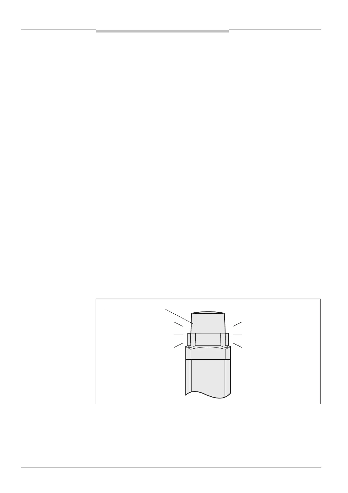
3.4.1 End cap with integrated LED (optional, only on receiver)
• The end cap with integrated LED is available only for the receiver of the M4000
Advanced and the M4000 Advanced A/P.
• The integrated LED is not monitored. This means that a failure of the integrated LED has
no effect on the function of the M4000.
Notes
Note
Notes
Fig. 11: End cap with
integrated LED
LED
AUDIN - 7 bis rue de Tinqueux - 51100 Reims - France - Tel : 03.26.04.20.21 - Fax : 03.26.04.28.20 - Web : http: www.audin.fr - Email : info@audin.fr

 Loading...


