Operating Instructions Chapter 6
M4000 Adv., Adv. A/P, Area
8010797/PA53/27-06-05 © SICK AG • Industrial Safety Systems • Germany • All rights reserved
43
Electrical installation
6 Electrical installation
WARNING
Switch the power supply off!
The machine/system could inadvertently start up while you are connecting the devices.
Ensure that the entire machine/system is disconnected during the electrical
installation.
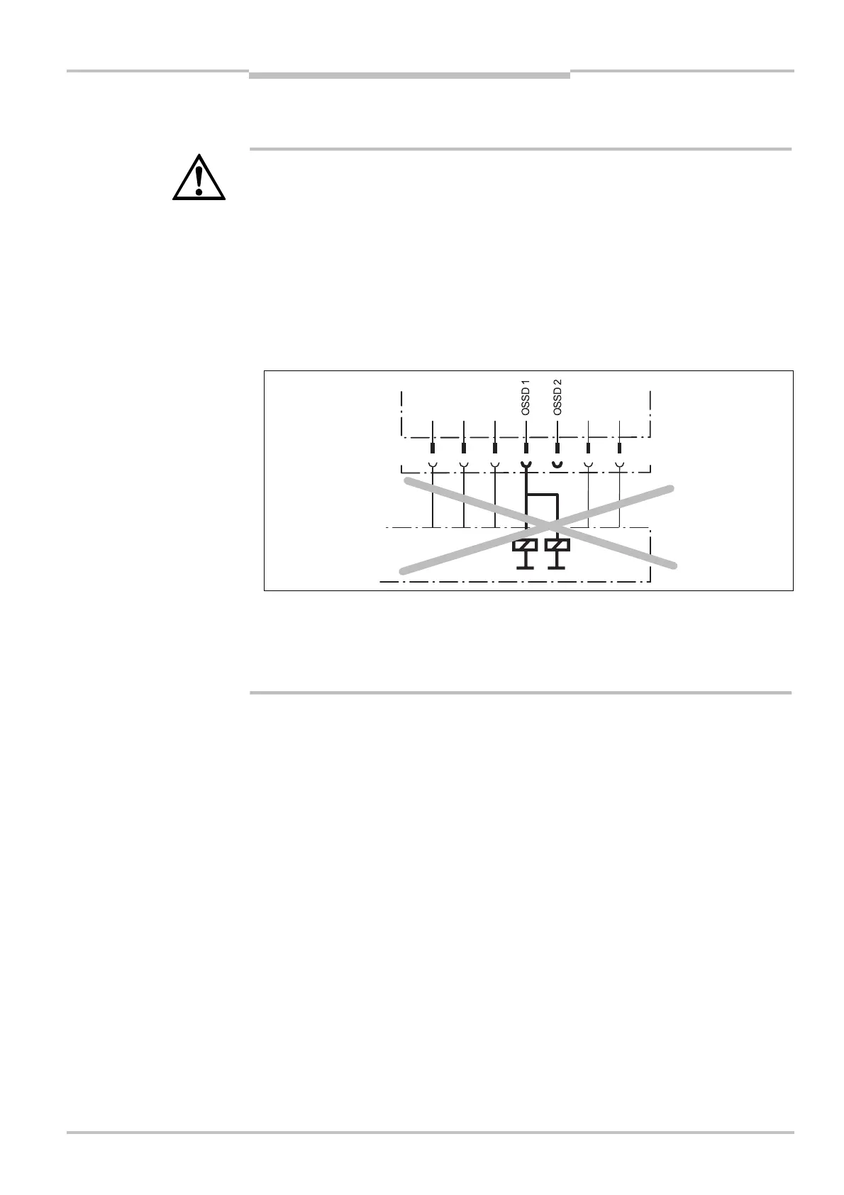
Connect OSSD1 and OSSD2 separately!
You are not allowed to connect OSSD1 and OSSD2 together, otherwise signal safety will
not be ensured.
Connect OSSD1 and OSSD2 separately to the machine controller.
Ensure that the machine controller processes the two signals separately.
Never connect more than one switching element to each OSSD!
You are only allowed to connect one switching element (e.g. relay or contactor) to each
output signal switching device (OSSD). If the application requires several switching
elements per OSSD, then you must use a suitable form of contact duplication.
• The two outputs are protected against short-circuits to 24 V DC and 0 V. When the light
path is clear, the signal level on the outputs is HIGH DC (at potential), when the light
beams are interrupted or there is a device fault the outputs are LOW DC.
• The M4000 multiple light beam safety device meets the interference suppression
requirements (EMC) for industrial use (interference suppression class A). When used in
residential areas it can cause interference.
• To ensure full electromagnetic compatibility (EMC), functional earth (FE) must be
connected.
• The external voltage supply of the devices must be capable of buffering brief mains
voltage failures of 20 ms as specified in EN 60204@1. Suitable power supplies are
available as accessories from SICK (Siemens type series 6 EP 1).
• The plug alignment (direction of turn) in the housing may vary from device to device. You
can identify the correct pin assignment by the position of the pins in relation to each
other as shown in the drawings.
Notes
AUDIN - 7 bis rue de Tinqueux - 51100 Reims - France - Tel : 03.26.04.20.21 - Fax : 03.26.04.28.20 - Web : http: www.audin.fr - Email : info@audin.fr

 Loading...


