Operating Instructions Chapter 7
M4000 Adv., Adv. A/P, Area
8010797/PA53/27-06-05 © SICK AG • Industrial Safety Systems • Germany • All rights reserved
53
Commissioning
7.2.1 Meaning of the 7@segment display during alignment
During alignment, the 7@segment display on the receiver shows you when the optimal
alignment is achieved (see Tab. 22).
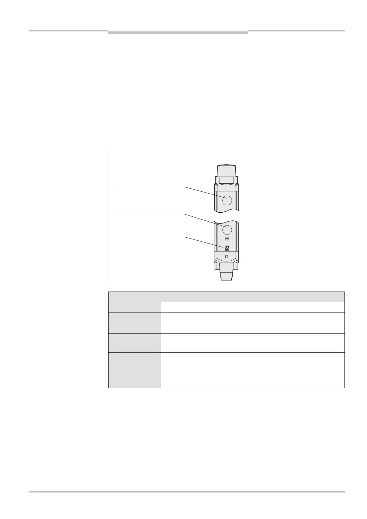
• The beam that is closest to the 7@segment display is termed the first light beam
(see Fig. 38 and Fig. 39).
• Only the first and last light beam are evaluated during alignment.
• If the optimum alignment (= no display) persists for longer than 2 minutes without the
multiple light beam safety device being interrupted, the system automatically
deactivates the alignment mode.
M4000 Advanced and M4000 Area 60/80
Display Significance during alignment
First and last light beam not aligned.
Only the first light beam is aligned.
Only the last light beam is aligned.
All the light beams hit the receiver, but the alignment is still slightly
off.
No indication and
green LED
illuminated on the
receiver
The alignment is now true; the devices must be locked in this
position.
Notes
Fig. 38: Illustration of the
beam order of the M4000
Advanced and the
M4000 Area 60/80
76segment display during
alignment of the
M4000 Advanced and the
M4000 Area 60/80
M4000 Advanced and M4000
Area 60/80
AUDIN - 7 bis rue de Tinqueux - 51100 Reims - France - Tel : 03.26.04.20.21 - Fax : 03.26.04.28.20 - Web : http: www.audin.fr - Email : info@audin.fr

 Loading...


