Operating Instructions Chapter 6
M4000 Adv., Adv. A/P, Area
8010797/PA53/27-06-05 © SICK AG • Industrial Safety Systems • Germany • All rights reserved
49
Electrical installation
WARNING
Device configuration after replacement!
If you replace a multiple light beam safety device with activated Reset function with a
replacement device, you must activate the Reset function again via the CDS. It is not
enough to only make the electrical connections.
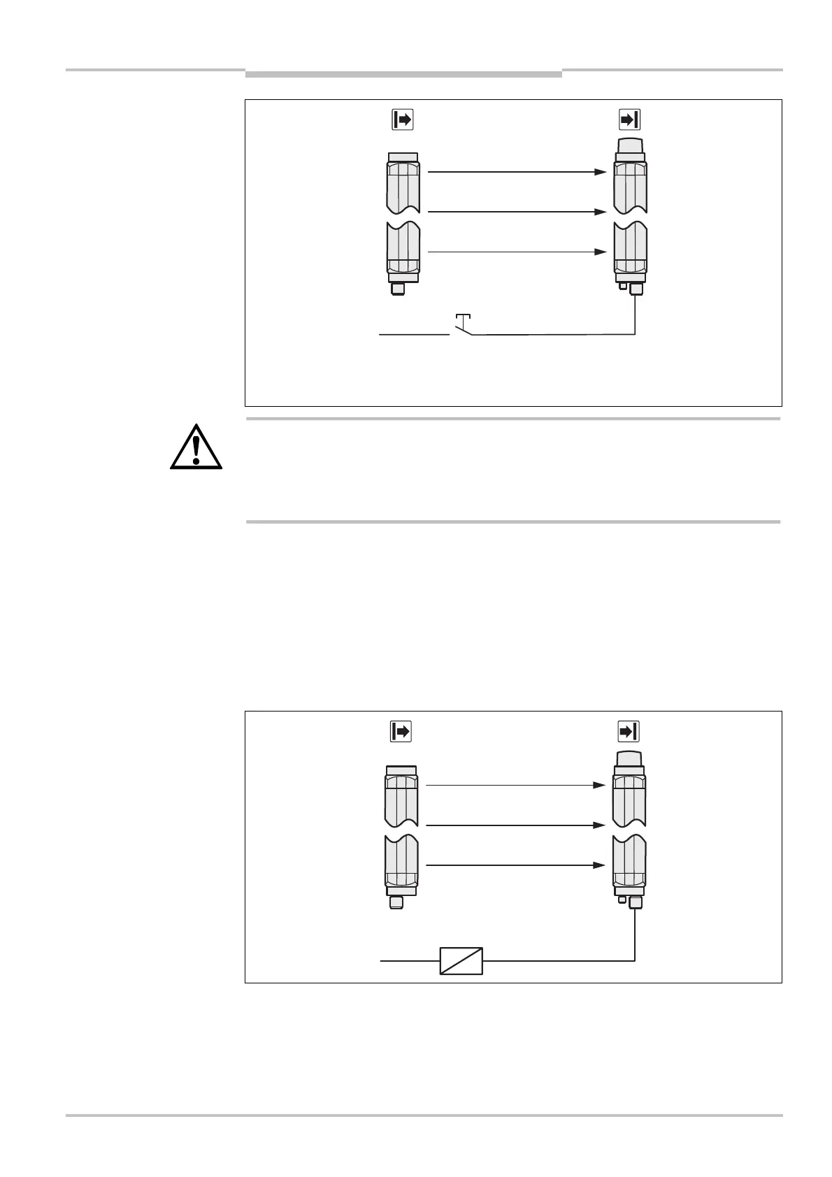
Connection of a Reset required signal lamp
Pin 8 of the system connection can be used as Reset required output (24 V). The output
has a frequency of 1 Hz.
6.6 Application diagnostic output (ADO)
Pin 7 on the system plug is an application diagnostic output (ADO). You can use this output
for a relay or a PLC.
Fig. 35: Connection of the
reset button
Fig. 36: Connection to the
application diagnostic output
AUDIN - 7 bis rue de Tinqueux - 51100 Reims - France - Tel : 03.26.04.20.21 - Fax : 03.26.04.28.20 - Web : http: www.audin.fr - Email : info@audin.fr

 Loading...


