Chapter 5
MSC800
70 Operating instructions | SICK 8011540/14B8/2019-06-06
Subject to change without notice
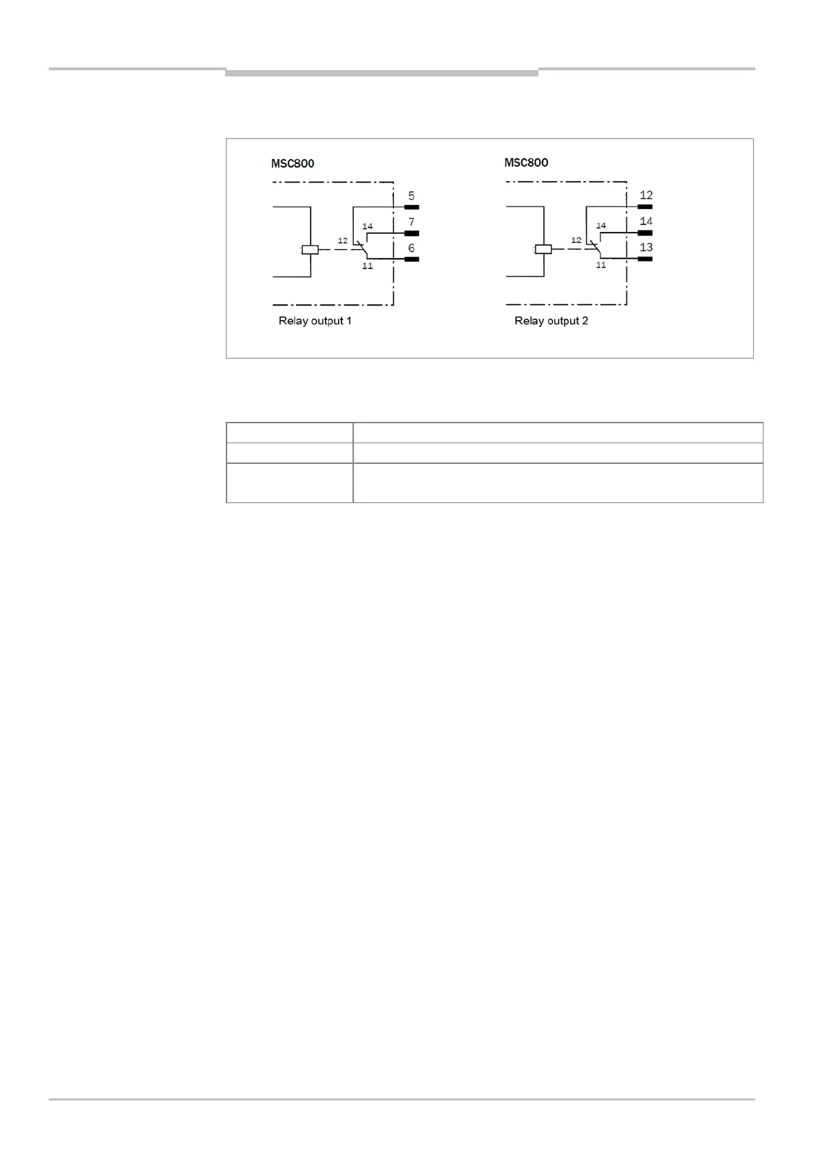
The figure below shows the wiring of relay outputs 1 and 2.
Fig. 29: Wiring of the relay outputs
The table below contains the identical characteristic data for the two relay outputs.
Switching behavior Changeover switch
Not short-circuit protected, not temperature protected
Electrical values U
Switch
≤ DC 30 V (protective extra-low voltage)
Switch
≤
Tab. 45 Characteristic data of the relay outputs
Wiring OUT switching outputs of the logic unit
Connect visualization device/PLC to one of the switching outputs OUT 1 to OUT 4, as
shown by way of example under wiring of the digital switching output OUT_1.
• In the “Device Ready” function, the output provides a static pulse when the MSC800 is
ready after initialization.
• In the “System Ready” function, the output provides a static pulse when the entire
system of MSC800 and ID sensors is ready.
For the thorough check of the switching functions, use a high resistance digital
voltmeter and wire the outputs with a load. This prevents the display of incorrect voltage
values/output states.
Important
Recommendation