TECHNICAL DATA 11
8027311 / V1-0/2022-04|SICK
Subject to change without notice
OPERATING INSTRUCTIONS|TDC-E (Telematic Data Collector)
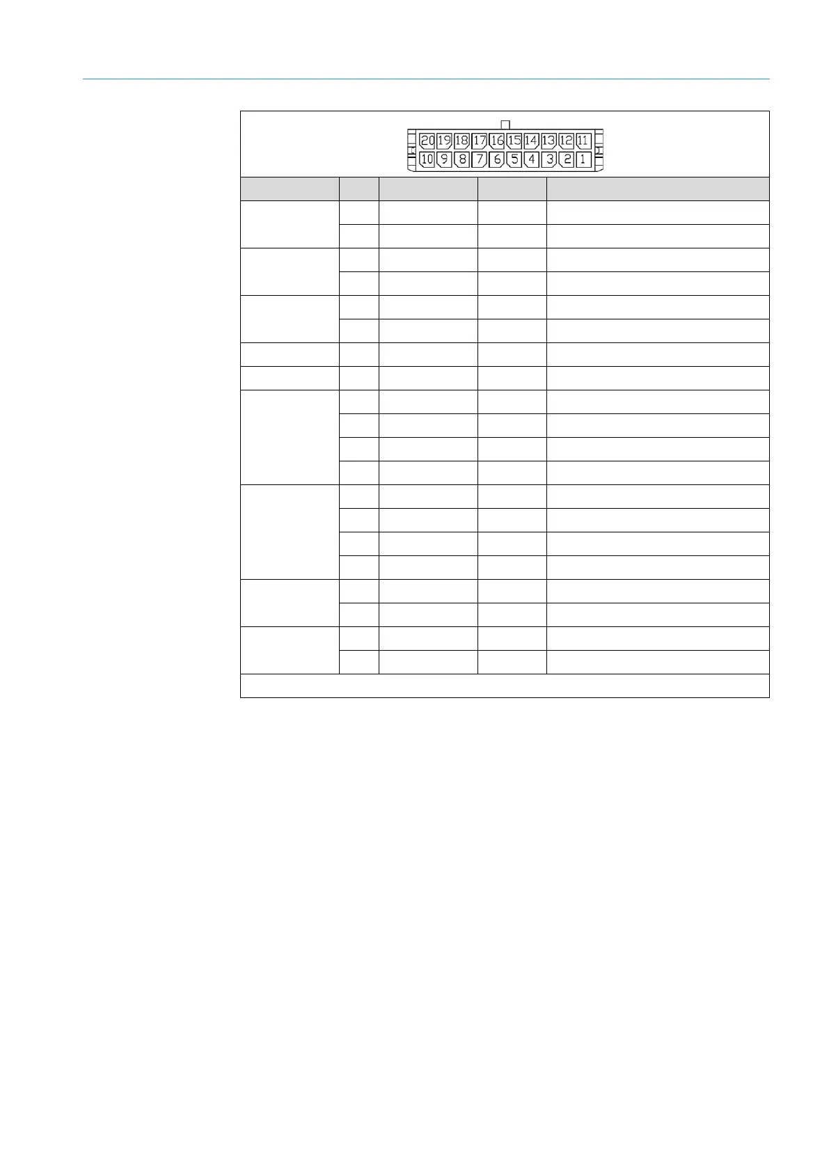
Group PIN Wire color Name Description
ADDITIONAL
DIO
20 Brown L+_A Used as a digital output
10 White-brown CQ_A Digital input
ADDITIONAL
DIO
19 Orange L+_B Used as a digital output
9 White-orange CQ_B Digital input
GND
18 Black GND Ground
8 Black GND Ground
+5 V DO 17 Red 5 V 5 V digital output
1-WIRE 7 Green-yellow 1 W 1-WIRE
RS-232
16 Yellow TX Cable for sending data
6 Gray RX Cable for receiving data
15 White-yellow CTS Clear to send
5 White-gray RTS Request to send
RS-485/
RS-422/
SSI*
14 Violet Y/CLK+ RS-485/422 / SSI data cable
4 White-purple Z/CLK- RS-485/422 / SSI data cable
13 Pink A/DATA+ RS-485/422 / SSI data cable
3 White-black B/DATA- RS-485/422 / SSI data cable
CAN A
12 White CANH_A CAN high – Channel A
2 Blue CANL_A CAN low – Channel A
CAN B
11 White-green CANH_B CAN high – Channel B
1 Green CANL_B CAN low – Channel B
* Configurable/RS-422 available in API
Tab. 15: COMM cable
• Half-duplex mode: The transceiver relies on the Y and Z pins in both send and receive
mode.
• Full-duplex mode: In receive mode, the transceiver uses the A and B pins; in send
mode, it uses the Y and Z pins.
COMM
cable
RS-485 / RS-422
pin assignment