11 TECHNICAL DATA
8027311 / V1-0/2022-04|SICK
OPERATING INSTRUCTIONS|TDC-E (Telematic Data Collector)
Subject to change without notice
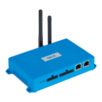
11.3 TDC-E pin assignments
Group PIN Wire color Name Description
PWR
14 Red VIN TDC-E supply voltage: 9 V–36 V DC
7 Black GND Ground
DIO
13 - - -
6 - - -
12 - - -
5 - - -
11 - - -
4 - - -
AIN
10 - - -
3 - - -
9 - - -
2 - - -
8 - - -
1 - - -
Tab. 13: PWR cable
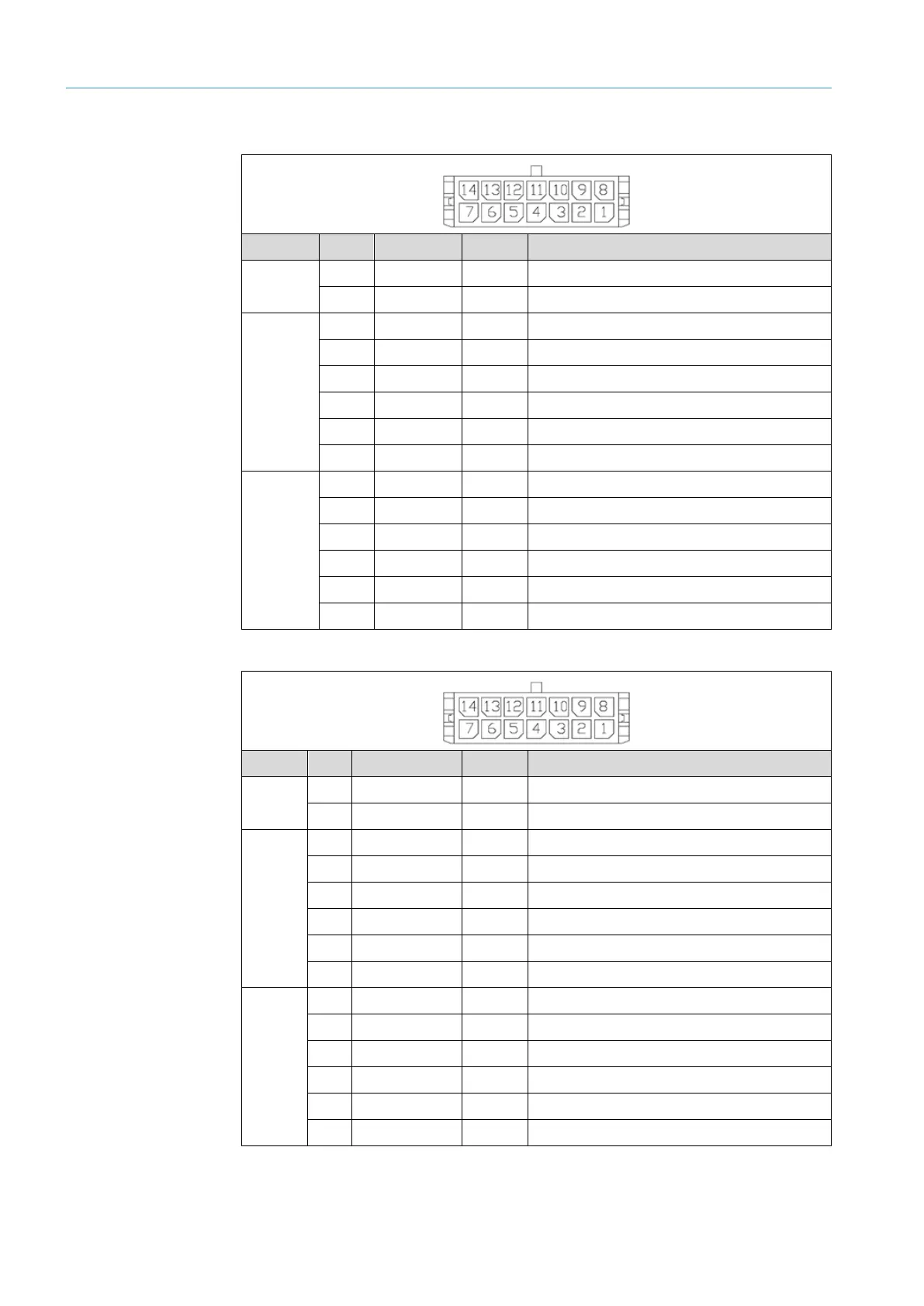
Group PIN Wire color Name Description
PWR
14 Red VIN TDC-E supply voltage: 9 V–36 V DC
7 Black GND Ground
DIO
13 Yellow DIO_A Digital input/output – Channel A
6 White DIO_B Digital input/output – Channel B
12 Blue DIO_C Digital input/output – Channel C
5 Pink DIO_D Digital input/output – Channel D
11 Gray DIO_E Digital input/output – Channel E
4 Violet DIO_F Digital input/output – Channel F
AIN
10 White-yellow AIN_A Analog input – Channel A
3 White-green AIN_B Analog input – Channel B
9 White-blue AIN_C Analog input – Channel C
2 White-red AIN_D Analog input – Channel D
8 White-gray AIN_E Analog input – Channel E
1 White-purple AIN_F Analog input – Channel F
Tab. 14: PWR+AIN/DIO cable
PWR
cable
PWR+AIN/DIO
cable