ELECTRICAL INSTALLATION 5
8027311 / V1-0/2022-04|SICK
Subject to change without notice
OPERATING INSTRUCTIONS|TDC-E (Telematic Data Collector)
5.1 Connection overview of TDC-E
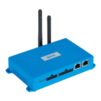
Fig. 17: Connections at the front
Legend
1 14-pin plug connection
• Voltage supply
• Digital inputs and outputs
• Analog inputs
2 20-pin plug connection
• Additional digital inputs and outputs
• RS-485/422, RS-232, SSI, 1-wire serial interfaces
• CAN
3 Eth0 for connecting Ethernet-capable sensors as well as connecting a
configuration PC (factory IP address: 192.168.0.100)
4 Eth1 for sending data via LAN (factory IP address: assigned by DHCP)
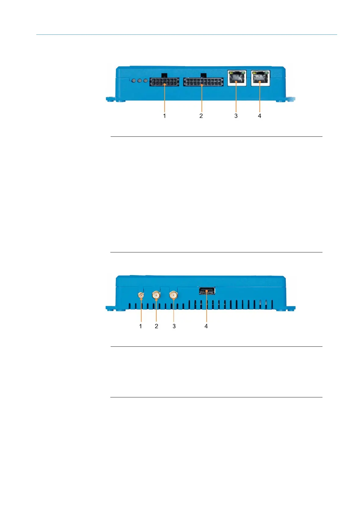
Fig. 18: Connections at the back
Legend
1 MCX female connector for connecting the GPS antenna
2 SMA female connector for connecting the LTE antenna
3 SMA female connector for connecting a WLAN antenna
4 USB 2.0 port
NOTE A detailed pin assignment can be found in the appendix.
Front
Back