5 ELECTRICAL INSTALLATION
8027311 / V1-0/2022-04|SICK
OPERATING INSTRUCTIONS|TDC-E (Telematic Data Collector)
Subject to change without notice
5.2 Connector
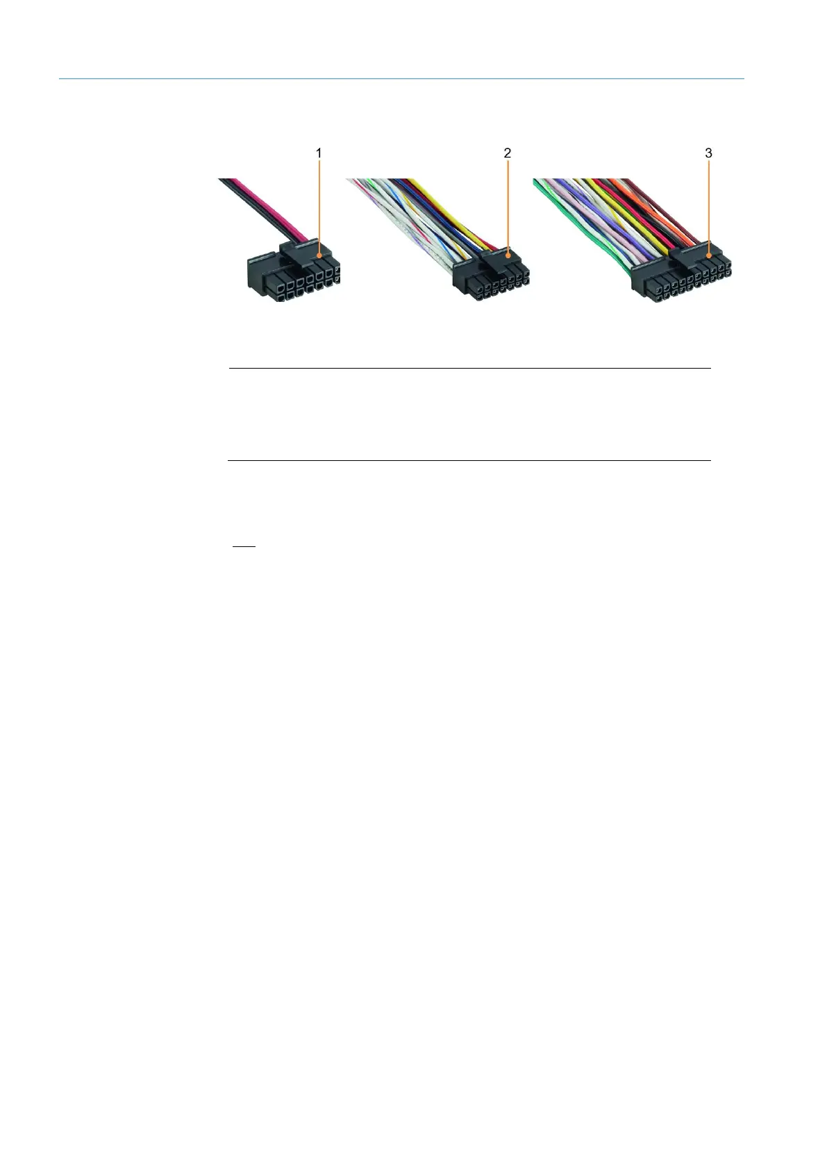
Fig. 19: Connector
Legend
1 14 pin Micro-Fit standard male connector
2 14-pin Micro-Fit add-on male connector (optional)
3 20-pin Micro-Fit add-on male connector (optional)
• The gateway system is delivered with a 14-pin Micro-Fit male connector as standard.
• Two cables have been routed out of this male connector at the factory so that the
device can be connected to the voltage supply.
• Only Ethernet-capable machines or sensors can be connected to the TDC-E with this
connector variant.
In the case of the 14-pin Micro-Fit male connector, the cable assembly has 14 color-
coded open-ended wires for connecting:
• Voltage supply (2 wires)
• Digital inputs and outputs
• Analog inputs
In the case of the 20-pin Micro-Fit male connector, the cable assembly has 20 color-
coded open-ended wires for connecting:
• Additional digital inputs and outputs
• RS-485/422, RS-232, SSI, 1-wire serial interfaces
• CAN
NOTE There is a pin assignment diagram for the connections on the bottom of the TDC-E
device.
▸
Please also refer to section 11.3 TDC-E pin assignments appendix.
Micro-Fit standard
male connector
14-pin Micro-Fit
male connector
(optional)
20-pin Micro-Fit
male connector
(optional)