SYSTEM DESCRIPTION 3
8027311 / V1-0/2022-04|SICK
Subject to change without notice
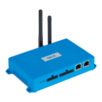
OPERATING INSTRUCTIONS|TDC-E (Telematic Data Collector)
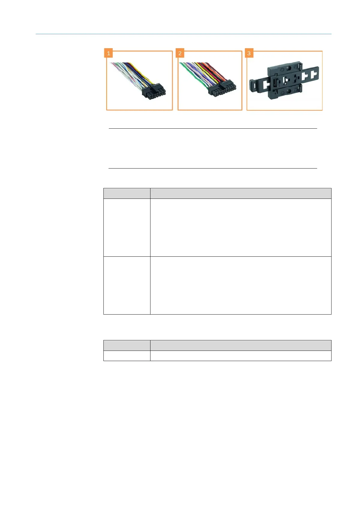
Fig. 2: Accessories (optional)
Legend
1 14-Pin Micro-Fit male connector
2 20-pin Micro-Fit male connector
3 DIN rail bracket
Preassembled cables can be purchased for connecting the sensors to the TDC-E devices.
Part no. Description
6068472 14-Pin Micro-Fit male connector with 14 color-coded wires with open
ends, length 90 cm.
Enables the connection of:
• Voltage supply (2 wires)
• Digital inputs and outputs
• Analog inputs
6068471 20-pin Micro-Fit male connector with 20 color-coded wires with open
ends, length 90 cm
Enables the connection of:
• Additional digital inputs and outputs
• RS-485/422, RS-232, SSI, 1-wire serial interfaces
• CAN
Tab. 1: Additional connecting cables (optional) – part numbers
A rail bracket is available for mounting the TDC-E on DIN mounting rails.
Part no. Description
6069266 DIN rail bracket for mounting the TDC-E
Tab. 2: DIN mounting rail bracket (optional)
Accessories (optional)