05.05 Function diagrams
SIEMENS AG 6RX1700-0AD76 8-7
SIMOREG DC Master Operating Instructions
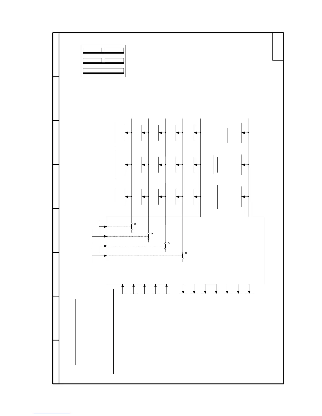
Sheet G101 Hardware configuration
87564321
- G101 -
CUDx
FD
E
G
1
32
0
1
0
1
0
1
0
1
r063.002
r063.003
r063.004
r063.005
r064.002
r064.003
r064.004
r064.005
r065.002
r065.003
r065.004
r065.005
U910.003
U910.004
U910.005
U910.002
r063.001 r064.001 r065.001
r060 r061 r062
P067
P075
P076
P077
P078
r068
r069
r070
r071
r072
r073
r074
Arrangement of board
locations 1 to 3 and slots
D to G in electronics box
Hardware configuration
Board code Board compatibility Software identifiers
Board in location 1
Board in slot D
Board in slot E
Board in slot F
Board in slot G
.001 CUD
.002 Slot D
.003 Slot E
.004 Slot F
.005 Slot G
.001 Year
.002 Month
.003 Day
.004 Hour
.005 Minute
.001 Converter firmware
.002 Boot sector
Software version
Checksum
Creation date
of software
Software
Load class
Control word for
power section
Reduction of converter
rated DC current
Total thermal
reduction factor
Reduction of converter
rated supply voltage
Options according to rating plate
Serial number
MLFB (order number)
Converter rated
supply voltage (armature)
Converter rated
DC current (armature)
Converter rated
DC current (field)
Converter rated
supply voltage (field)
Definition of SIMOREG DC Master power section
Select / deselect slots

 Loading...