05.05 Function diagrams
SIEMENS AG 6RX1700-0AD76 8-35
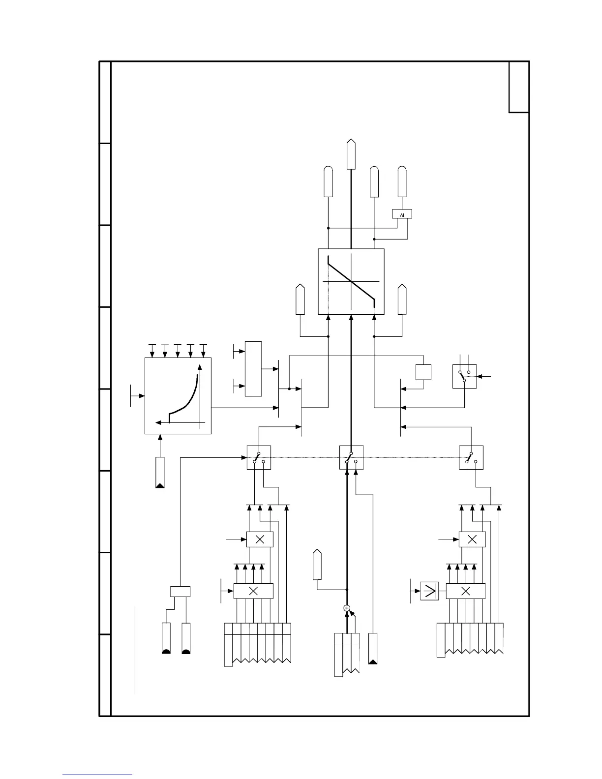
SIMOREG DC Master Operating Instructions
Sheet G161 Current limitation
1
0
1
≥
.01
.02
.03
.04
1
0
1
0
x
y
x
y
.03
.04
0
∗ -1
.05
87564321
- G161 -
1
.06
.07
.01
.02
.03
.04
.05
.06
.07
[G180.8]
[G182.7]
[G151.3]
[G160.3]
[G160.8]
[G162.1]
[G163.2]
P075 P077
P104 (n1)
P105 (i1)
P106 (n2)
P107 (i2)
P108 (n3)
P109 (0)
K0133
K0147
P604 (9)
K
K
K
K
K0131
K0120
K0132
K0166
B0161
B0111
P601
K
K
134
K
B0200
B0194
B0195
P171.F *)
(100,0%)
P603
K
K
K
K
K
K
K
1
1
1
1
1
2
2
P172.F *)
(-100,0%)
P100.F
________
r072.002
P100.F
________
r072.002
K
K
Current limitation
I limit
|n act|
Speed-depend. current
limit
I²t monitoring of
power section
Minimum
9=neg. signal effective
acc. to P603.xx
-150% * P077
(4Q converter)
0%
(1Q converter)
Armature
current setpoint
Lowest pos.current limit
"+Ia_limit"
Highest pos.current limit
"-Ia_limit"
Shutdown
Emergency stop
Min.
pos. current limit
neg. current limit
Absolute
actual speed
Minimum
Maximum
*) With these parameters, 100% corresponds to the
rated motor armature current (P100)
Current limitation active
Armature current controller
setpoint before current limitation
1Q/4Q converter
Max.
FS
Pos. current limit reached
Neg. current limit reached
(see Section 9)
FS
Min.
Min.
Max.
Max.

 Loading...