05.05 Connections
Siemens AG 6RX1700-0AD76 6-13
SIMOREG DC Master Operating Instructions
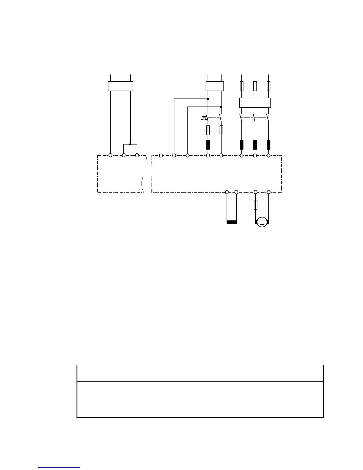
6.1.2.3 Arrangement of components for converters
Arrangement of reactors and RI suppression filter
1U1 1V1 1W13U1 3W15U1 5W1
1C1 1D1
M
3C 3D
1)
2)
3)
4)
5N1
NC
400V230V
5U1
5W1
5N1
5)
Line voltage
Field ArmaturePower supply input
either 230V or 400V
SIMOREG-converter
1) The commutating reactor in the field circuit is dimensioned for the rated motor field current.
2) The commutating reactor in the armature circuit is dimensioned for the motor rated current in
the armature.
The line current equals DC times 0.82.
3) The RI suppression filter for the armature circuit is dimensioned for the motor rated current in
the armature.
The line current equals DC times 0.82
4) The RI suppression filter for the electronics power supply alone with 400 V is dimensioned
for ≥1A.
The RI suppression filter for the field circuit and electronics power supply with 400 V is
dimensioned for the rated current of the motor field plus 1A.
5) The RI suppression filter for the electronics power supply with 230 V is dimensioned for ≥2A.
CAUTION
When RI suppression filters are installed, commutating reactors must always be inserted
between the filter and device input to decouple the surge suppression circuits and protect the X
capacitors.
The commutating reactors must be selected from Catalog DA93.1. The RI suppression filters
must be selected from Catalog DA93.1 or according to the table of EPCOS filters below.

 Loading...