Emergency operation
17
Siemens Building Technologies 007831_a_en_--.doc
Fire & Security Products 03.2004
4.1 Emergency operation at line module E3M111 level
– Alarm evaluation in ”Emergency operation” mode via Emergency operation
processor and ”Emergency operation” in the detector
– With emergency alarm a ”Collective alarm” is given at the B3Q700 with the re-
sponse indicator in the detector flashing
– With line short circuit and malfunction of the line processor no ”Emergency
alarm” is given
4.2 Emergency operation at line module E3M080 level
– Alarm evaluation with ”Emergency operation” via hardware comparators
– With emergency alarm the ”Collective alarm” is given at the B3Q700 without the
response indicator at the detector flashing
– Selectable Function ”Short circuit = Alarm” also fulfilled with emergency alarm
4.3 General requirements
At least one control console per system must comply with standard EN54, i.e. must
have Emergency operation capability and Emergency power supply.
Emergency power supply
– This consists of a second supply circuit to stations located elsewhere
– For this purpose the B3Q700 has 2 de-coupled supply inputs
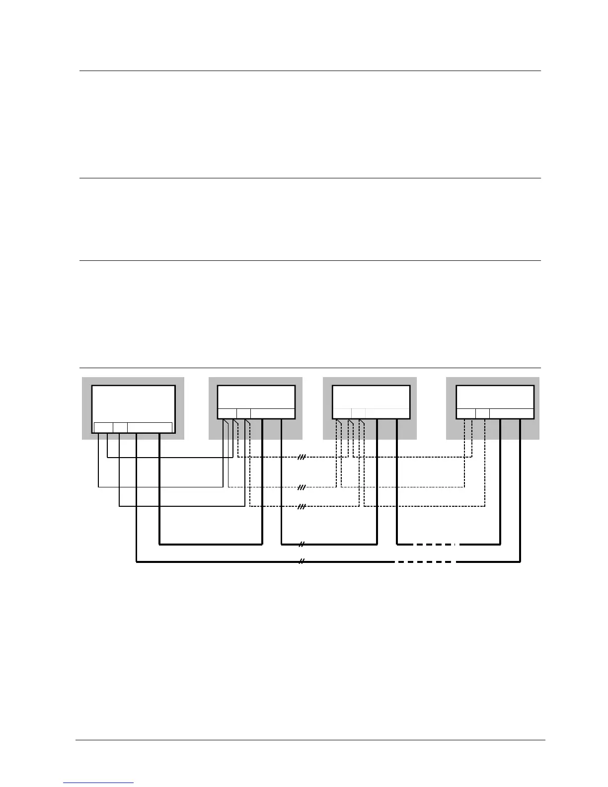
4.4 Wiring principle
C-Bus
K5
K7 K6 A1/B1A2/B2
K5 K5
K7 K6 A1/B1A2/B2 K7 K6 A1/B1A2/B2
B3Q700 (CPU)
'FC'
K5
K7 K6 A1/B1A2/B2
B3Q700
'FT'
B3Q700
'FT'
B3Q700
'FT'
C-Bus return line
C-Bus loop line = max. 1000m (at G51 ø 0.6mm) incl. return line or max. 1400m at G51 ø 0.8mm
Supply circuit 2
(Emergency supply)
Supply circuit 1
Emergency operation circuit
1)
1)
Two requirements must be met for control consoles located elsewhere. At least
one control console must comply with standard EN54 (i.e. have emergency opera-
tion capability and emergency supply).
EN54 requirements:
Communication as loop line
(= C-Bus designed as loop line)
Operation also in emergency mode
(= 3 additional wires for emergency operation
between CPU and control consoles)
Second de-coupled 24V supply
(= 3 additional wires if there is no autono-
mous power supply)