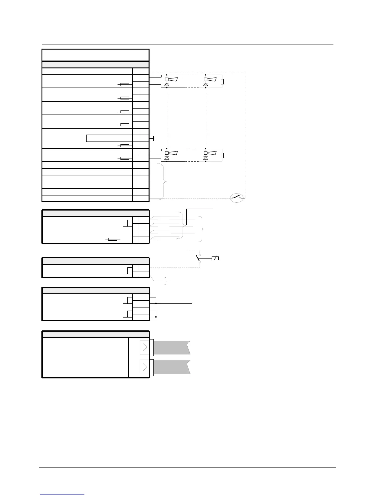
E3G060 Control module ”Monitored”
70
Siemens Building Technologies 007831_a_en_--.doc
Fire & Security Products 03.2004
17.7 Connections
(connect to chassis ground)
Monitored
control line 1
E3G060
1
2
3
4
5
6
7
8
9
10
11
12
-
+
-
+
-
+
-
+
-
+
13
14
15
16
-
+
17
18
19
20
F1
H1LED
Module chassis ground
Terminal block
X1
common for inputs 15... 20
F3
H2LED
F5
H3LED
F7
H4LED
control inputs:
to invert global defined horn mode
(switch S7) individually for each horn
output from (constant / intermitted)
F9
H5LED
F11
H6LED
4.75k
Ω
24V
max. 2A
4.75k
Ω
24V
max. 2A
2
3
4
+
+
Plug-in terminals
K1
to other I-Bus modules
Supply for
I-Bus modules
from previous I-Bus modules
1
blue
blue
green
red
24V
5V
Double flat cable header
ST1
Data communication
I-Bus modules
to other I-Bus modules
from previous I-Bus modules
Monitored
control line 2
Monitored
control line 3
Monitored
control line 4
Monitored
control line 6
Monitored
control line 5
F19
2
Plug-in terminals
K2
Horn Synchronization output or
Horn oscillator input
1
2
3
4
+
+
Plug-in terminals
K3
External horn supply
24V / 12A (only external supply)
1
24V / 12A
0V
time relay (external horn oscillator)
(Relay / contact must not be outside the
control unit housing)
to other E3G060 (for horn synchronization)
(all E3G060 in the same housing)
GND
-
-
-
-
1)
1