E3G070 Control module ”Universal”
73
Siemens Building Technologies 007831_a_en_--.doc
Fire & Security Products 03.2004
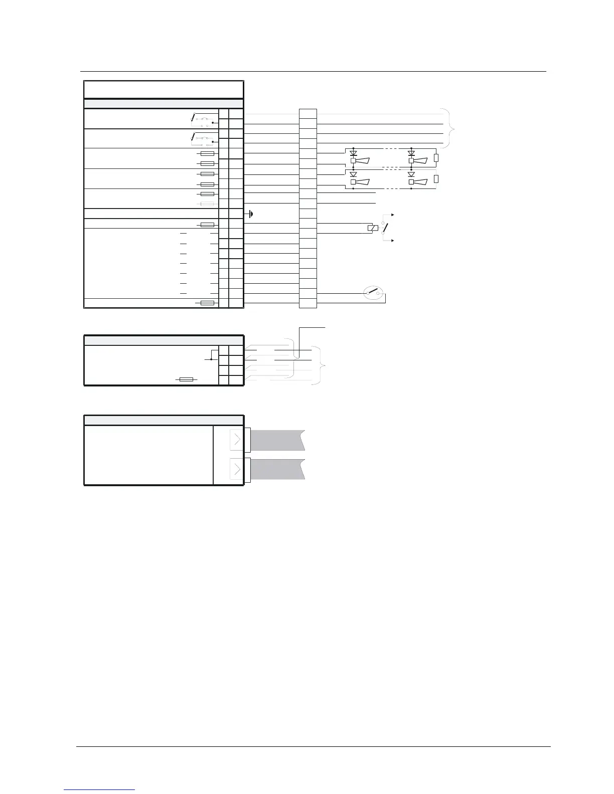
18.5 Connections
Inputs / outputs
24V 40mA
Alarm horn 2,
monitored control line
Alarm horn 1,
monitored control line
Remote
transm. alarm
E3G070
1
2
3
4
5
6
7
8
9
10
11
12
+
-
+
-
+
-
+
13
14
15
16
-
-
-
-
17
18
19
20
-
-
-
F9
to remote
transmission equipment
max. 24W (60V 1A)
F3
F4
Y12
X12
K1
F6
F7
F8
F2
F5
Q1/I1
24V
4.75k
Ω
max. 2A
4.75k
Ω
Function output
Relay / contact must not be outside the
control unit housing
Function input
H1LED
H2LED
H3LED
H4LED
(connect to
chassis ground)
K2
Y13
24V
max. 2A
Supply output remote transmission
Module chassis ground
+24V
0V
Terminal block
X1
Q2/I2
Q3/I3
Q4/I4
Q5/I5
Q6/I6
Q7/I7
LED
LED
LED
LED
LED
LED
LED
H5
H6
H8
H9
H7
H10
H11
X13
Remote transm. fault
(Shown in normal operation)
1)
1)
The indicated polarity at the terminals 5...8 applies to the active state
2)
The output X1-9,10 is always monitored
3)
Terminate not used horn lines with a 4,75k
Ω
resistor
to teletransmission unit or to other
internal
load
2)
3)
1
Terminal block X1
2
3
4
5
6
7
8
9
10
11
12
13
14
15
16
17
18
19
20
2
3
4
+
+
Plug-in terminals
K1
Supply for
I-Bus modules
to I-Bus module E3M111
from I-Bus module E3C011
1
blue
blue
green
red
24V
5V
Double flat cable header
ST1
Data communication
I-Bus modules
F1
GND
-
-
to I-Bus module E3M111
from I-Bus module E3C011
26 pin26 pin
default connection of
E3G070 at Pos. 38