E3G070 Control module ”Universal”
72
Siemens Building Technologies 007831_a_en_--.doc
Fire & Security Products 03.2004
18.3 Important components
H1
H8
X60
X12
Y12
Y13
F6
F7
F8
F9
S2
ST1
S3
F4
F3
F2
K2
F5
X13
F1
ON
1
ON
K1
1
4
0 -Resistors
Ω
"Y12" = Remote transmission alarm as make contact (factory setting)
"X12" = Remote transmission alarm as break contact
"Y13" = Remote transmission fault as break contact (factory setting)
"X13" = Remote transmission fault as make contact
Fuse
F1 5A/T Module supply
Fuses
F2, F3 0,63A/T Supply output
F4, F5 0,25A/T Control outputs / inputs
F6...F9 2A/T* Control lines for alarm devices
* Fuse with high breaking capacity (sand-filled)
Flat cable header "ST1" (26-pin): I-Bus
Plug-in terminals "K1":
Supply for "I-Bus" modules
Maintenance switch"S2":
To switch on maintenance LEDs for test
purposes. In addition to driver output,
enables the corresponding LED (H1...H11)
to be activated.
= LED (H1..H11) lights if output
is activated.
S2-on
Programming switch "S3":
"I-Bus address" setting (see below)
Connector "K2"
unused
Test LEDs H1...H11 at rear.
Allocation of the individual LEDs
see chapter Connections
Jumper "X60":
Ground fault monitoring 'control unit
''out' = inactive (factory setting)
'in' = active
(for application details see chapter
Ground fault monitoring)
E3G070
ASIC
I-Bus
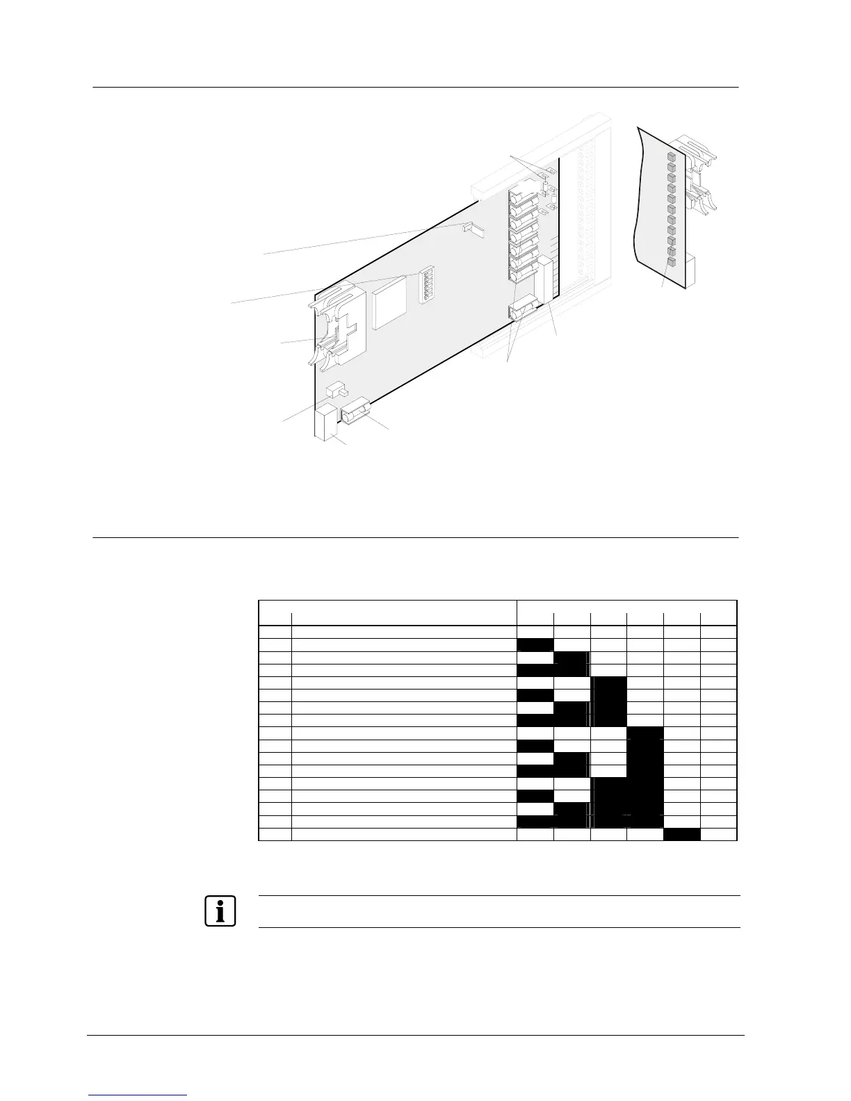
18.4 Programming switch ”S3”
To set I-Bus address. Each element (module) connected to the I-Bus must have an
individual address (number). This is set on programming switch ”S3”. Maximum 16
I-Bus devices.
Function / I-Bus address Programming switch S3
No. S3-1 S3-2 S3-3 S3-4 S3-5 S3-6
0 Module out of commission (unused) off off off off off off
1 I-Bus user number 1 on off off off off off
2 2 off on off off off off
3 3 on on off off off off
4 4 off off on off off off
5 5 on off on off off off
6 6 off on on off off off
7 7 on on on off off off
8 8 off off off on off off
9 9 on off off on off off
10 10 off on off on off off
11 11 on on off on off off
12 12 off off on on off off
13 13 on off on on off off
14 14 off on on on off off
15 15 on on on on off off
16 16 off off off off on off
”S3-1...6” are set to ”off” at the factory
The I-Bus address setting is given as default by the tool (SWE700A) as address 15, therefore the
programming switch 'S3' of the E3G070 must be set accordingly.